Πλέγμα Χαρακτηριστικά μονάδας σύνδεσης ασύρματης μετάδοσης αμφίδρομης μετάδοσης
- Μονάδα πλέγματος σύνδεσης ασύρματης μετάδοσης διπλής κατεύθυνσης OFDM
- Προμήθεια 3 Θύρα Ethernet ασύρματης διαφανούς μετάδοσης,1 Ασύρματη διαφανής σειριακή θύρα μετάδοσης,1 Διαμόρφωση σειριακής θύρας
- Διπλές κεραίες: κύριες και βοηθητικές κεραίες, που μπορεί να διαμορφωθεί ως διπλή εκπομπή και διπλή λήψη, μονή εκπομπή και διπλή λήψη, ή απλή μετάδοση και απλή λήψη.
- Υποστηρίξτε ασύρματες ζώνες συχνοτήτων εργασίας:566~678MHz、1420~ 1530 MHz, υποστηρίζει αυτόματο άλμα συχνότητας εντός και μεταξύ των ζωνών συχνοτήτων
- Ασύρματο εύρος ζώνης με δυνατότητα διαμόρφωσης:1.4MHz、3MHz、5MHz、10MHz、20MHz、40MHz, η μέγιστη ταχύτητα διεπαφής αέρα μπορεί να φτάσει τα 100 Mbps
- Μέθοδος διαμόρφωσης:QPSK/QAM16/QAM64 Αυτόματη προσαρμογή
- Μέγιστη ισχύς μετάδοσης:23±2dBm(2 δρόμος)
- Ευαισθησία:-102dBm(1Εύρος ζώνης Mbps@20MHz)
- Υποστήριξη κρυπτογράφησης και αποκρυπτογράφησης ασύρματων συνδέσμων
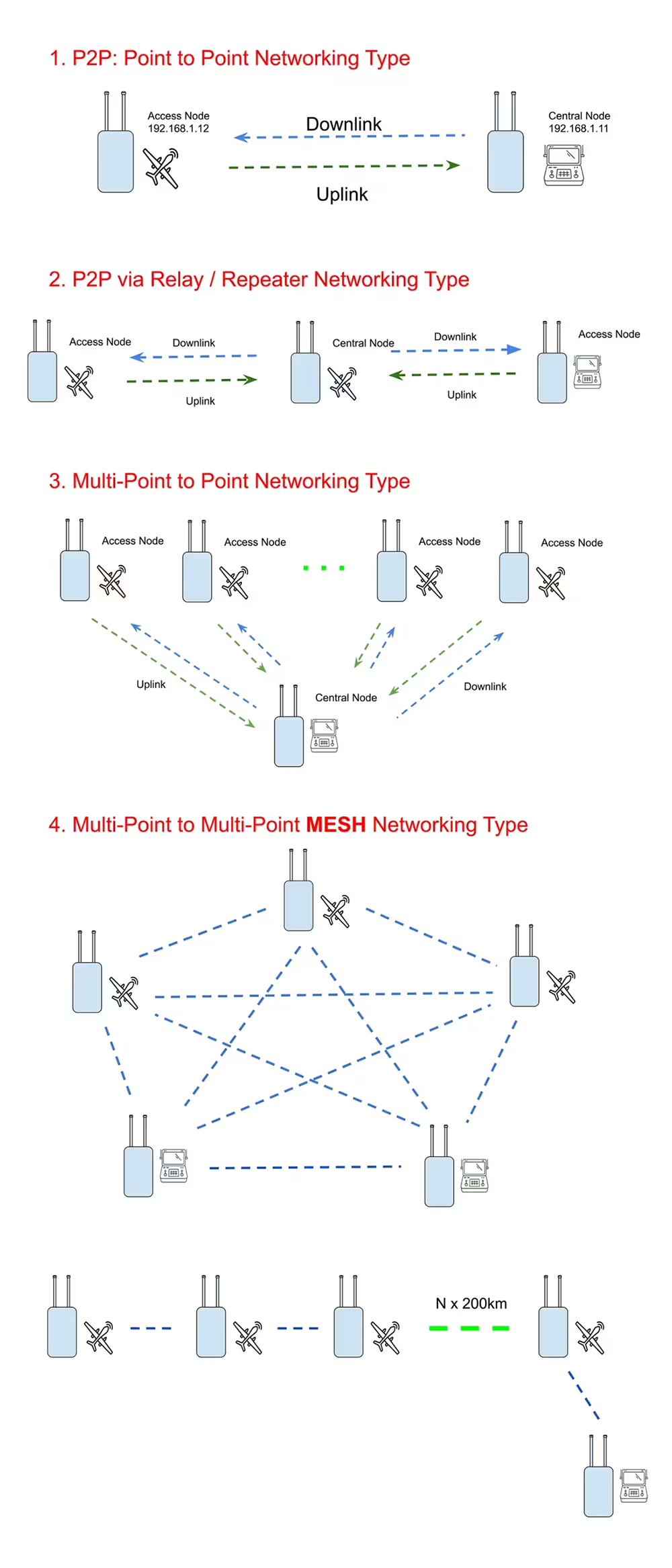
- Υποστήριξη ασύρματης ad hoc μεθόδου Mesh Communication, δίκτυο έως 32 κόμβων.
- Όλες οι επικοινωνίες κόμβων μοιράζονται το εύρος ζώνης εργασίας και τον μέγιστο ρυθμό κοινής χρήσης του συστήματος 100 Mbps. Διανείμετε προσαρμοστικά τις τιμές συστήματος εξίσου.
- Υποστηρίζει τοπολογία δρομολόγησης πολλαπλών βημάτων, έως 32 κόμβους31 Δρομολόγηση μετάβασης. Η σταθερή διαμόρφωση διαδρομής υποστηρίζεται και ισχύει μόνιμα.
- Υποστηρίξτε την υψηλότερη ταχύτητα κίνησης 300 km/h.
- Τύπος δείκτη καθυστέρησης μονής κατεύθυνσης(Κυρία): 6*Η + (5/2) * N/2 * Η * 3, η αμφίδρομη καθυστέρηση πολλαπλασιαζόμενη με 2 (N είναι ο αριθμός των κόμβων μέσα σε δύο άλματα, ο αριθμός των λυκίσκων H). Βελτιστοποιημένη καθυστέρηση μεταξύ δύο κόμβων: Καθυστέρηση μονής κατεύθυνσης μονής μετάβασης μεταξύ δύο κόμβων≤10ms;Καθυστέρηση βελτιστοποίησης αλυσίδας τεσσάρων κόμβων: τεσσάρων κόμβων μονόδρομη καθυστέρηση τριών βημάτων μονής μετάβασης≤10ms; 6 Δίκτυο αλυσίδας σημείων,3 λυκίσκος, one-way delay50ms;8 σημεία, one hop for all points, one-way delay36ms;8 σημεία, serial7 hop, one-way delay170ms;32 σημεία, one hop for all points, one-way delay120ms;32 σημεία, serial31 Jump one-way delay3750ms。
- Logical master node power-on network construction delay20s~80s(There are no restrictions on modules. Generally, the logical master node is powered on first.);Cold start, delay from node startup to network access<30s Received logical master node signal; hot start, slave node startup network access delay<1Εάν αυτό το αντικείμενο βρίσκεται στην κατοχή σας περισσότερο από(Ordinary one-hop node networking scenario);Hot start, power on the node from a single frequency point and connect to the network<480Κυρία + 160ms*H(H is the hop count)。
Υποδοχή μονάδας σύνδεσης ασύρματης μετάδοσης με πλέγμα διπλής κατεύθυνσης
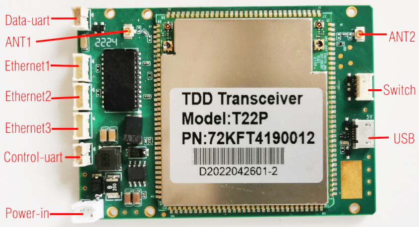
- Data-uart: Data transparent transmission serial port, default RS232 level(It can also be changed to TTL level),3PIN 1.25mm Space between seats.
- Ethernet1: Two-way wireless transparent transmission network port,4PIN 1.25mm Space between seats.
- Ethernet2: Two-way wireless transparent transmission network port,4PIN 1.25mm Space between seats.
- Ethernet3: Two-way wireless transparent transmission network port,4PIN 1.25mm Space between seats.Ethernet1、Ethernet2 and Ethernet3 It’s a bridge method,IP The address is the same.
- Control-uart: Configure serial port,TTL 3.3V level,3PIN 1.25mm Space between seats.
- ANT1: Main antenna interface,IPEX seat. The antenna works on TDD Transceiver mode. Regardless of whether the system is 2T2R、1T2R or 1T1R operating mode, the antenna is always TDD Transceiver mode.
- ANT2: Auxiliary antenna interface,IPEX Seat. The antenna can be configured as TDD Transmitting and receiving mode, it can also be configured as an auxiliary receiving mode that only transmits without transmitting. When the system is working 1T2R In mode, the antenna does not transmit and only assists in reception.
- Power-in: Power input interface,2PIN 2.0mm spacing seat, support 9~28V Wide voltage input, maximum power consumption is less than 6 W.
- USB: Micro USB Seat, for system maintenance.
- Switch:receive/Send switching signals for connecting to external Power amplifier module.
- 12V out:Είσοδος ευρείας τάσης,12V Regulated voltage output(current less than150mA), used to power the cooling fan.
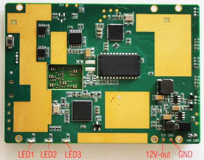
- LED1: Red power indicator light, always on when power is supplied normally.
- LED2: Blue indicator light.
- LED3: Green indicator light.LED2 and LED3 The working status is as follows:
| master node | blue LED2 The indicator light is always on, green LED3 The indicator light does not light up |
| Other nodes | green LED3 The indicator light stays on after the link is successfully established. |
| Blue LED2 Indicator light indicates wireless link signal strength Wireless link signal strong: blue LED2 indicator light 30 Flash once per second; Wireless link signal fair: blue LED2 indicator light 6 Flash once per second; Wireless link signal weak: blue LED2 indicator light1 Flash once per second; |
- The Mesh Module size 80*57mm, the front device height is less than5mm, the height of the back device is less than2.5mm, plate thickness1.6mm,weight 41g。
- The Mesh Module passed Web UI Or configure the serial port AT Parameter query, configuration and management are carried out in command mode.
Πλέγμα Δικατευθυντική μονάδα ασύρματης ζεύξης μετάδοσης Περιγραφή σήματος διεπαφής
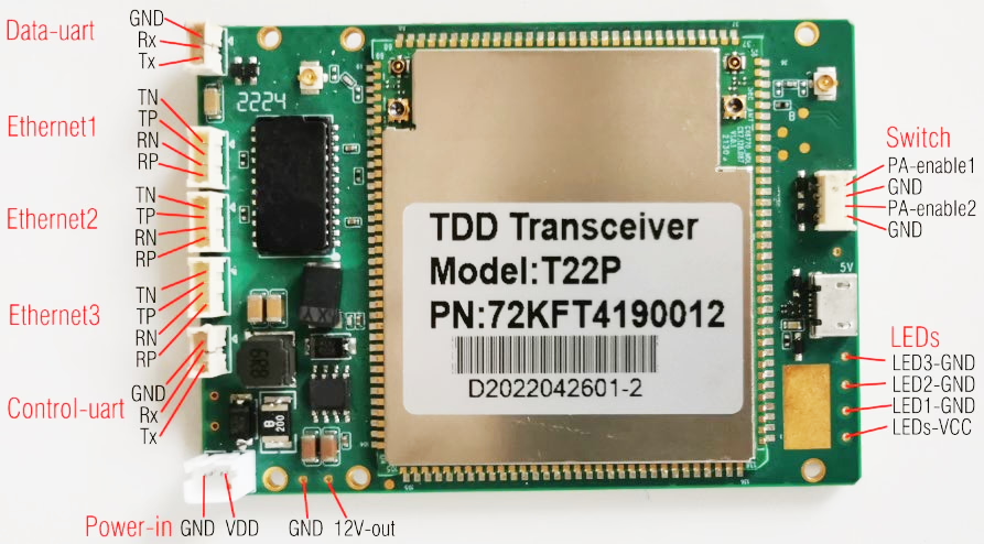
εισόδου ισχύος,3 individual 4PIN network port,3PIN Data-uart、3PIN Control-uart,Switch interface,12V See the figure above for details of output and other signal annotations.
Data-uart
Two-way wireless data transparent transmission serial port, default RS232 level,3PIN 1.25mm Space between seats. Default setting Data-uart The highest priority in wireless link data transmission(Higher than audio and video data, network port data and other port data), the lowest delay.Data-uart Serial port data is wirelessly transparently transmitted to the serial port of other docking nodes in the wireless network.
Control-uart
System management configures the serial port,TTL 3.3V level,3PIN 1.25mm Space between seats. Can be used through this serial port AT command pair the Mesh The module performs parameter configuration, wireless link status query and management, και τα λοιπά.
Switch διεπαφή
The maximum transmit power of the mesh module itself is 23±2dBm, it can be extended through the external power amplifier. The module increases the transmit power. This interface is used for external expansion. The mesh module provides an enable signal(Two-way enable)。
| Signal | power domain | I/O | Function description | Παρατήρηση |
| PA-enable1 | 1.8Β | THE | High level sending, before sending starts3.19us Pull high, after sending0.26us Pull low. | Send high and close low |
| PA-enable2 | 1.8Β | THE |
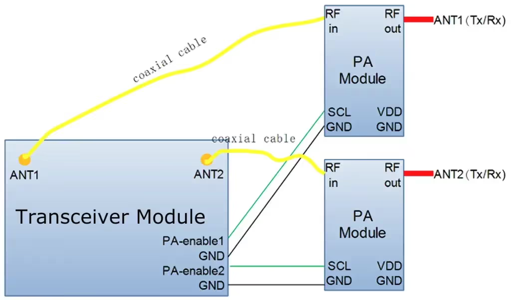
We provide various models of power amplifier modules for this mesh module, which can increase the overall transmit power to 2W、5W or 10W. The docking diagram is as follows:
LED Welding hole
The Mesh Module onboard has 3 individual LED indicator light(LED1/LED2/LED3). Sometimes it is necessary to pull the indicator light to the equipment shell panel. Σε αυτήν την περίπτωση, you can use LEDs Solder hole solder connection wire connects the indicator light mounted on the panel to the Mesh module board. The corresponding signals are as follows:
| ενδεικτική λυχνία | εικονογραφώ | Corresponding welding holes |
| LED1 | Power indicator light | LED1-GND and LEDs-VCC |
| LED2 | Wireless link working indicator light | LED2-GND and LEDs-VCC |
| LED3 | LED3-GND and LEDs-VCC |
Πλέγμα Module application
Κάντε μια ερώτηση
Το μήνυμά σας έχει σταλεί