Питання: What is details of the serial port buffer protection chip on COFDM video transmitter?
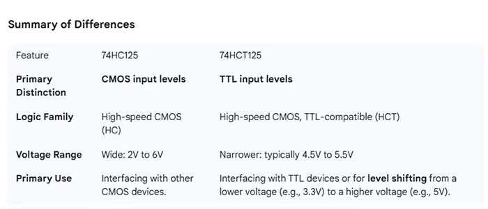
The most recent COFDM video transmitters have shown some connection issues. We replaced the buffer chipset you provided, and the issue was resolved. Could you provide the specifications of the chipset? We intend to buy it locally. Do you think using TTL input might be better, since we’ve been having a lot of trouble with the 74HC2G125DC, which uses CMOS input? The model name, 4HCT2G125DC, has an extra “Т”. Can you review it again?
Відповідь: Thank you for your feedback regarding the COFDM video transmitter. We understand that you experienced connection issues, which were resolved after replacing the buffer chip.
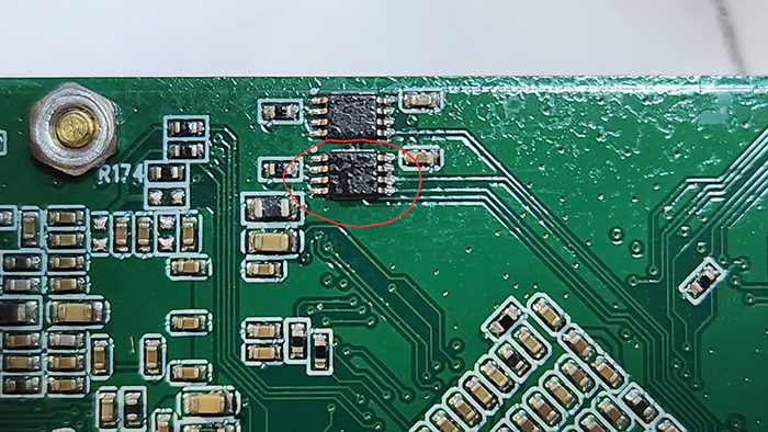
The serial port buffer protection chip used on our COFDM video transmitter is SN74AUP2G125DCUR. Please find below the schematic diagram and datasheet for your reference. This is the schematic diagram and chip datasheet of the serial port buffer protection chip of the COFDM video transmitter.

Please check, what is the voltage level of your device connected to the serial port of our encoder board? Наприклад, some serial ports use TTL 5V, but the buffer chip of TI on the board recommends that the serial port level of the other end is TTL 3.3V.
We recommend not plugging or unplugging serial port cables while the system is powered on, as this can also damage the chip.
About the part
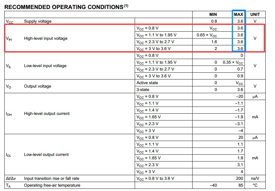
SN74AUP2G125DCUR is a TI single-supply, 2-channel bus buffer/driver with output enable. It is optimized for low-voltage systems (typical use at 1.2–3.6 V depending on variant). It provides input/output buffering and is small and low-power. (If you need the exact electrical limits, check the datasheet for absolute maximum ratings and recommended operating conditions.)
User-facing causes of failures (most likely → less likely)
- Hot-plugging / plugging/unplugging while powered
- Even if nominal levels are 3.3V, connecting or disconnecting serial cables while the unit is powered can create voltage transients or momentary voltages beyond the device limits and cause immediate or latent damage.
- ESD (electrostatic discharge)
- ESD events during handling, assembly, or field operations commonly damage small logic chips. Outdoor use or handling without ESD precautions increases risk.
- Voltage transients from external equipment
- External devices (older TTL equipment, converters, adapters) can produce short overvoltage pulses, negative transients, or spikes on TX/RX lines that exceed the chip’s absolute ratings. Even brief pulses can degrade the device.
- Ground potential differences / connector ground not common
- If the encoder board and the connected device do not share a stable reference (common ground), common-mode voltages can stress the buffer inputs.
- Cable-related issues (long cables, poor shielding, connecting to inductive loads)
- Long unshielded serial cables pick up noise and transients; abrupt switching of nearby RF power amplifiers can couple into lines.
- Connector or wiring faults
- Miswires, intermittent connectors, exposed pins, or poor solder joints can cause short pulses or reverse voltages into the chip.
- Corrosion / вологи / contamination
- Outdoor deployments (вологість, salt spray) or contaminated connectors cause leakage paths and intermittent currents that damage inputs.
- Thermal / environmental stress
- Repeated thermal cycling or prolonged high temperature can accelerate failure modes. Field devices near heat sources are more vulnerable.
- Over-voltage from other attached signals (Vcc back-driving)
- If the external device drives the line when the board Vcc is absent or lower (for instance during power sequencing), current can flow into the chip’s IO and cause damage.
- Counterfeit, reflow damage, or poor lot quality
- Parts from unreliable sources, or components damaged during soldering/assembly, show higher failure rates. Check lot codes and supplier traceability.
Practical user-side precautions
- Avoid hot-plugging: always power down both sides before connecting/disconnecting serial cables. Make this a user instruction and sticker near the connector if possible.
- Use a known-good cable: short, shielded cables with secure connectors reduce transients and noise pickup. Replace suspect cables.
- Confirm common ground: verify a solid ground reference between devices before operation. If using external power supplies, tie grounds first (with power off).
- Limit handling without ESD protection: use wrist straps, grounded benches, or at minimum avoid direct contact with bare pins. Train crew in ESD precautions.
- Use protective caps and keep connectors clean: when not in use, cover connectors; inspect for corrosion or bent pins.
- Power sequencing procedure: ensure the external device isn’t driving lines before the board’s Vcc is up. Document the correct on/off sequence for users.
- Inspect connectors and harnesses: regularly check for loose pins, broken locks, or exposed conductors. Replace worn connectors.
- Avoid running serial cables near high-power RF or switching supplies: route them away from antennas, PAs, or switching regulators.
- Keep replacement parts from trusted suppliers: buy from authorized TI distributors and log lot numbers for returned-fault tracing.
- Record failure conditions: when a unit fails, note exact operating state (power on/off, recent cable actions, surrounding equipment active, weather) and keep the failed part for supplier analysis.
- Simple field protections (user-installable): inexpensive inline series resistors (Напр., 47–100Ω) and small plug-in TVS/ESD protectors at the connector can reduce stress without PCB changes—these can be placed on the cable or connector shell.
What to collect when a failure occurs (for supplier/vendor claim or root cause analysis)
- PCB serial number / lot number and chip lot code (if readable).
- Date/time and operating conditions (powered on/off, nearby RF activity, cable operations).
- Photos of connector and board area (for corrosion or mechanical damage).
- Which external device was connected (model and its voltage levels).
- Any error logs or symptoms (intermittent, permanent, occurred after shock).
- Failed part (keep the chip and board) for supplier failure analysis.
Задавати питання
Дякуємо за вашу відповідь. ✨