
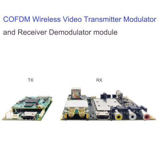
Decode board H265 COFDM Wireless Video transmission Receiver


Sell Points
- Low-latency audio and video decoding and playback, maximum support for 1080P@60 real-time audio and video decoding
- COFDM wireless receiving video stream input, H.265 decoding, HDMI, AV, USB/Ethernet simultaneous output video stream
- Ethernet input video stream, H.265/H.264 decoding HDMI and AV output
- Support multi-channel video decoding playback, split-screen display
- Can store the received video stream, recording files with time information (with RTC function)
- Two-way audio function
Function
- It realizes H.265 or H.264 video decoding and playback function, supports 1080P@60fps decoding and playback at the maximum, and is compatible with other various resolutions and frame rate decoding and playback. The decode board can be used with the H265/H264 encoding board and the COFDM transmit/receive module to realize low-latency high-definition digital wireless video transmission. The actual test video delay can be 60ms~200ms. The delay refers to the delay from the HDMI video input of the transmitting end to the HDMI video output of the receiving end, excluding the delay of the front-end camera of the transmitting end (we measured the delay of a certain brand SLR camera in about 70ms and the delay of a well-known brand sports camera in about 130ms).
- Support microphone input audio
- Support video decryption function (matching with transmitter video encryption)
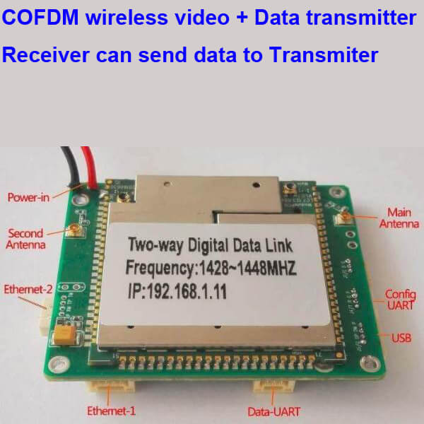
- Parameter configuration serial port (Config UART): can be connected to PC or parameter control panel for parameter configuration, or can be connected to another host computer for parameter configuration (such as drone remote control), Config UART is TTL 3.3v level.
- Transparent data transmission serial port (Data UART), TTL 3.3V level.
- USB Host Type-A port
- The USB Host interface can be connected to a USB flash drive or USB hard drive to store video, and the recorded file has time information. On-board RTC, system time can be set and saved.
- The USB Host interface can be connected to a smartphone or tablet, and the demodulated video stream is transmitted to the mobile phone/tablet through the USB interface for decoding and display. We provide Android APP and SDK and can support customers to develop their own apps on Apple iOS.
- TF card interface (for software upgrade maintenance, data storage, etc.)
- Ethernet port: video input or output interface
- 3 LED lights: power indicator, wireless link work indicator, record indicator
- Preset dual antenna COFDM receiver module docking interface
- Preset RCD dual antenna two-way wireless link module docking interface
- ANT1 and ANT2: Connect the IPEX antenna interface of the Received module to the SMA carrier
- Two buttons:
- Key1 – OSD On / Off,
- Key2 – Video Recording On / Off
- Size 85.6 x 79.6mm (excluding the dimensions of the interface device and the connector extension board)
- Decode board thickness is 1.6mm, the front component is less than 7mm, the back component is less than 2.5mm
- Supply voltage: 7V~24V
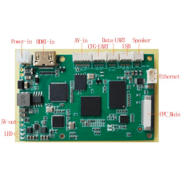
Interface:
HDMI-A type port audio and video output
- AV audio and video output (4PIN)
- USB Host interface output to mobile phone or tablet (future)
- Ethernet interface output (future)
- Supports simultaneous output of HDMI and AV, and supports demodulated video stream output to USB/Ethernet interface at the same time.
Interface Define
Power input interface (Power), AV output interface (AV)
The power input interface is a 2PIN 2.0mm pitch socket that supports a DC voltage of 7~24V. The AV output connector is a 4PIN 2.0mm pitch socket. The signal definitions of the power input interface and the AV output interface are as follows:

Data UART, Config UART, Microphone Input ( Microphone in)
The Data UART is a 3PIN 1.25mm pitch socket with a set of TTL serial ports. The Config UART is a 4PIN 1.25mm pitch socket that contains a set of TTL serial ports and provides 5V external power supply signals. Mic in is a 2PIN 2.0mm pitch socket. The signal definitions of the data serial port (Data UART), the configurable serial port (Config UART), and the microphone input interface (microphone in) are shown in the figure below.

Ethernet interface (Ethernet)
The Ethernet interface adopts 4PIN 2.0mm pitch socket or direct soldering hole. The signal definition is shown in the figure below. This Encode board can output the demodulated video stream of the DR2C COFDM wireless receiving module to the PC or NVR device through the Ethernet interface for decoding and playback. This Encode board can also input video streams through the network port for low-latency decoding playback. For different applications of the Ethernet port, you may need to program different Decode Board firmware. If you need it, please contact us.

LED lights and buttons
There are 3 LED lights onboard, and each LED light is defined as follows:
| Signal name | Description | Note |
| Power-LED | Power input indicator | Red Light |
| Link-LED | Wireless link status indicator (lights up after system startup, blinking during normal operation of the wireless link) | Green Light |
| REC-LED | Record video indicator (always on when recording video) | Green Light |
The Key2 button is a video recording on/off button (Record button), and long-press the button to switch the state. After this Decode Board detects the storage device, it starts recording and preferentially records to the TF card. If the TF card is not inserted, it is recorded to the USB flash drive. If they are not inserted, they will not be recorded. The recorded video file has time information. On-board RTC, system time can be set and saved through the configuration of the serial port.
The Key1 button superimposes the text information on the on/off button (OSD button) displayed on the video screen. When the OSD button status is “Off”, text information is not superimposed on the video screen. When the OSD button status is “On”, text information is superimposed on the video screen. Press and hold the OSD button to switch the switch state, and the switch state will be powered off. When the SHD5 board is shipped, the OSD display function is disabled by default. If you need to open the OSD display function, please use this button to switch the OSD display status.
When the OSD display status is turned on, it will be displayed in red in the upper left corner of the output video screen:
RF: 338.0MHz BW: 4.0MHz; RF indicates the center operating frequency, BW indicates the working bandwidth
QPSK CR: 2/3 GI: 1/16; QPSK is the modulation mode, CR is the convolutional code rate, and GI is the guard interval.
AIR: 3.90Mbps; AIR is the air interface rate
VBR: 3.05Mbps AES OFF; VBR is the video bit rate, AES OFF means no encryption
S1:27 S2:22; S1 refers to the signal strength received near the HDMI port antenna, and S2 refers to the other antenna.
B1: 0.14% B2: 100.00%; B1 refers to the BER error rate near the HDMI port antenna, and B2 refers to the other antenna.
REC OFF No Storage; REC OFF means no video storage
When the wireless receiving signal is interrupted, the output video screen will be interrupted (the re-received signal screen will be automatically restored), and it will display:

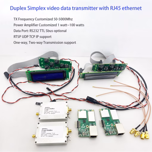
This decode board can be flexibly used with other COFDM Wireless Video receiver modules. This decode board can be separately assembled with the DR2C COFDM receiving and demodulating module and the RCD two-way wireless link module to form a wireless receiver with different functions, and realize wireless signal receiving demodulation and audio and video decoding output.
1) This decode board is equipped with another DR2C dual-antenna COFDM receiver demodulation module to form a complete COFDM receive decoding function.

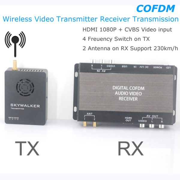
2) This Decode board assembly another RCD two-way wireless link module, used as a two-way wireless link video receiver, supports wireless one-way video transmission decoding display, two-way wireless voice, two-way wireless serial port data transmission, two-way wireless network port data Transparent transmission function.


3) The Config UART interface of this Decode board can be connected to the serial port control panel for setting operating parameters such as working frequency band, wireless bandwidth, and receiving the password. We provide SconA, SconB, SconC and other models with reference panels for customers to choose. See the documentation of the matching panel for details.
4) This Decode Board can also input video stream through network port for H265/H264 decoding playback output. This Decoder board supports multi-channel video decoding and split-screen display. The software can program the corresponding version firmware according to user needs. For such applications, please contact us if you have a need.


isdb-t.com_buyer –
This H.265 COFDM decode board is an absolute powerhouse and the heart of my wireless video reception system. The setup was incredibly straightforward, and I was impressed by how quickly it integrated with my existing hardware. Video decoding is exceptionally smooth and efficient; the H.265 compression delivers stunningly sharp, high-definition video with remarkably low latency, even in challenging NLOS (Non-Line-of-Sight) environments. The signal stability is rock-solid, maintaining a flawless stream without any dropouts or artifacts. It handles continuous operation without overheating, proving its robust build quality. For anyone building a professional-grade wireless video link that demands reliability, exceptional picture quality, and efficient bandwidth use, this decode board is an outstanding and highly recommended solution. It truly exceeds expectations.