
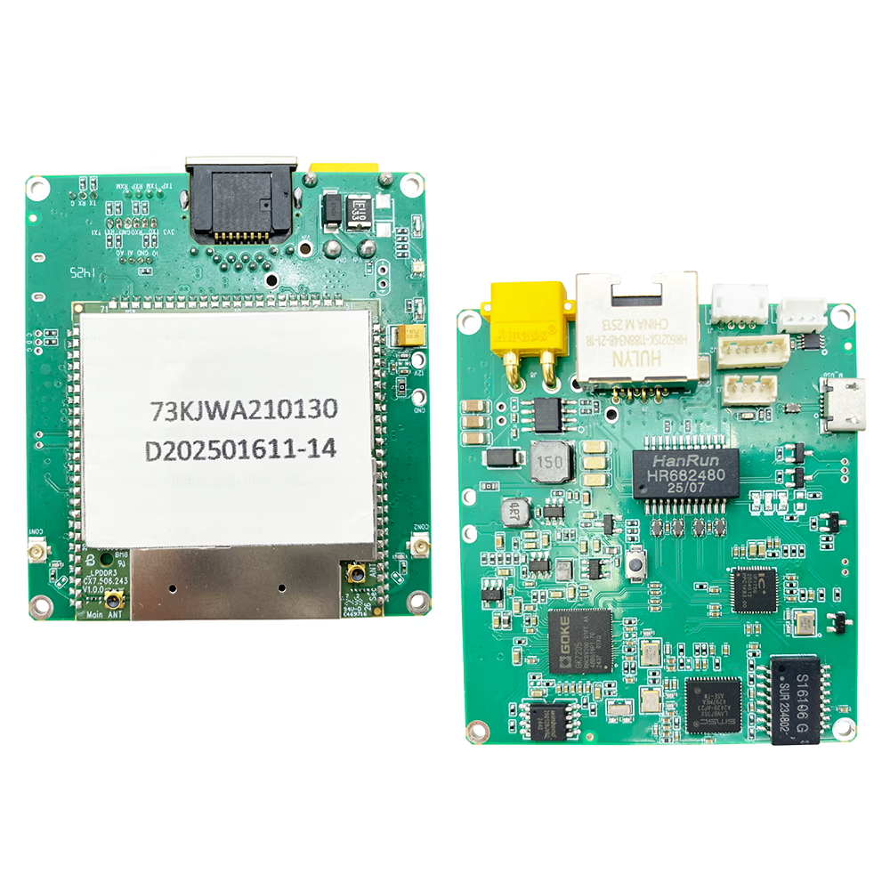
DIY UAV drone video data radio link module IP TTL Sbus
Overview
Introducing the DIY UAV drone video data radio link module support IP TTL Sbus — a high-performance, bidirectional transceiver module combining video transmission, data telemetry, and radio control for UAVs, drones, or any aerial/ground robotics platform. Engineered for long-range use, this module delivers robust communication links, offering flexibility, reliability, and scalability in demanding environments. Whether you’re doing FPV video, remote sensor telemetry, or controlling multiple nodes in a mesh network, the IS1681 is designed to be a powerful all-in-one communications solution.
Features
-
Full-Duplex / Bidirectional Link
The IS1681 supports two-way communication, meaning it can simultaneously handle downlink (video + data from UAV to ground station) and uplink (control, telemetry, commands) streams. This ensures low latency remote control as well as real-time feedback. -
Flexible Frequency Bands
Supports operation on multiple RF bands: ~800 MHz (806-826 MHz), ~1.4 GHz (1428-1448 MHz), and ~2.4 GHz (2402-2482 MHz). This flexibility allows system integration in crowded RF environments, and options to optimize for longer propagation (lower frequency) or higher bandwidth (higher frequency) depending on mission needs. -
Selectable Bandwidth & Modulation
Multiple channel bandwidth options are available: 3 MHz, 5 MHz, 10 MHz, and 20 MHz, permitting trade-offs between range, data throughput, and robustness. Modulation schemes include QPSK, 16-QAM, and 64-QAM, automatically adapting to channel conditions. -
Long-Range Transmission Capability
In line-of-sight (LOS) conditions, the module delivers ranges up to ~17 km without an additional external power amplifier. With added PA/amp modules, ranges extend significantly, depending on power and antenna configuration. The module’s max RF power is 25 ± 2 dBm by default. -
High Sensitivity Receiving
The module exhibits excellent receiving sensitivity across all supported bands. For example, at 1 Mbps data rate, sensitivity hovers around –106 dBm to –108 dBm depending on the band. This helps in maintaining communication integrity over longer distances and in noisy environments. -
Multiple Interfaces & Transparent Transmission
-
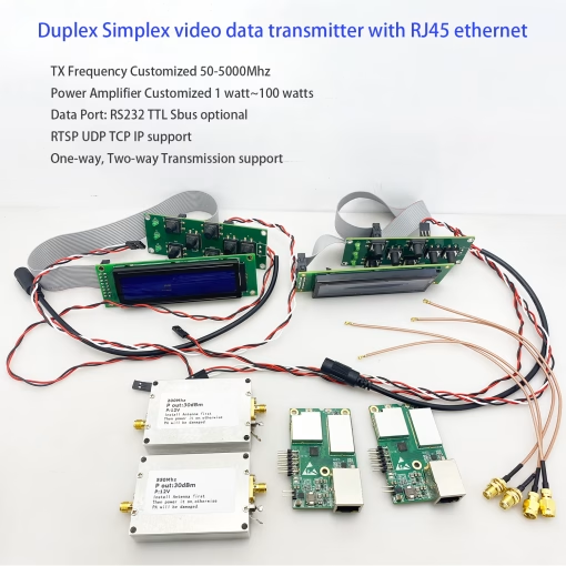
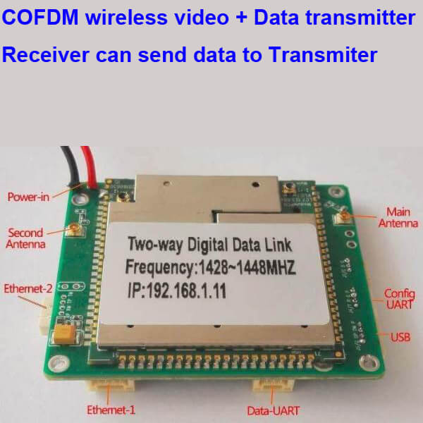
Dual Ethernet ports (one 4-pin ZH connector, one RJ45) for IP networking / transparent Ethernet bridging.
-
Multiple UART / TTL serial ports (3 x UART/TTL, including one dedicated control/data channel).
-
Audio input and output (line/mic in, earphones/speaker out) with on-board codec for two-way audio communication.
This assortment of I/O allows seamless integration with onboard flight controllers, video encoders, remote user interfaces, etc.
-
-
Network Modes & Scalability
The IS1681 supports multiple networking topologies: point-to-point, point-to-multipoint, star network, relay/repeater/extender, and mesh network (IP mesh). Up to 16 access nodes can connect to a central node in some configurations, sharing bandwidth as per link capacity. This is useful for distributed systems, large surveillance setups, mapping swarms, etc. -
Security & Management
-
AES-128 encryption ensures data privacy and resistance to eavesdropping.
-
Management can be performed via Web UI or UART commands.
-
Uplink/downlink stream ratios are configurable, allowing control of how much bandwidth is assigned to video vs telemetry vs control signals.
-
-
Physical Specs, Power & Robustness
-
Operating temperature: –20 °C to +65 °C; storage temperature: –40 °C to +80 °C.
-
Wide input power range: typically 7-30 V DC, consuming < ~4.5 W in normal operation.
-
Compact form factor (≈ 58×64×13 mm), weight ≈ 32 g. Dual antennas (main & aux) supporting MIMO type reception.
-
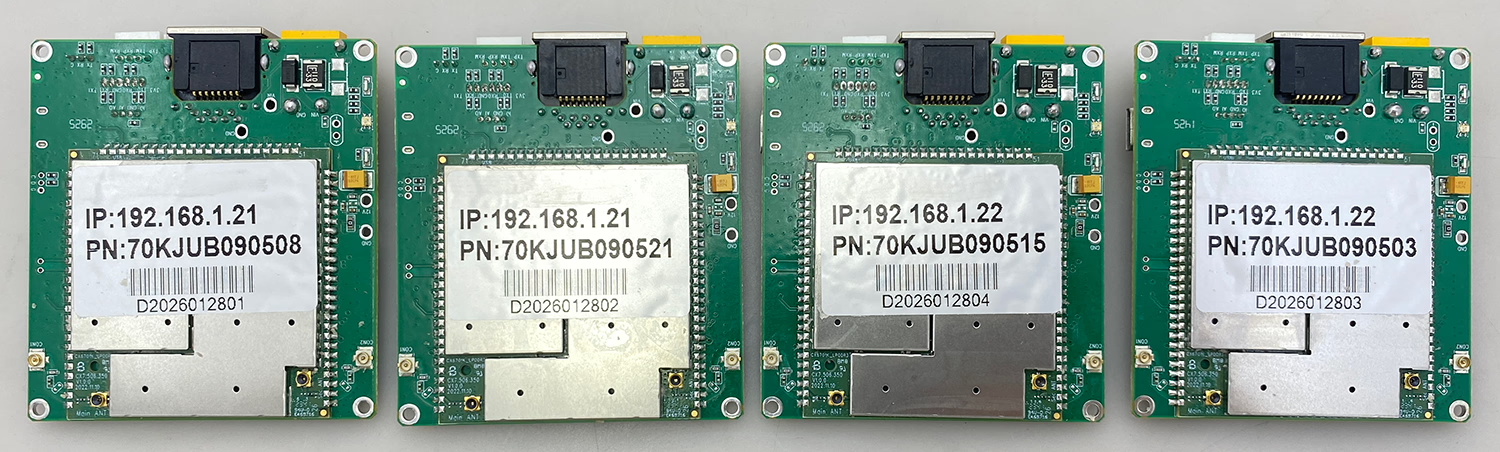
Interfaces & Connectors
Here’s what you’ll find on the module, and how you can hook it up:
-
Power input: XT30PW-M connector, accepting 7-30 V DC.
-
Ethernet ports:
One port via 4-pin ZH1.5 mm connector;
One RJ45 port (also supports transparent IP traffic). -
Serial / UART / TTL ports: Multiple ports at TTL 3.3 V, including one that can serve control or data role.
-
Audio I/O: 4-pin PH1.25 mm connector, with line/mic in, line/speaker out, for two-way audio use.
-
Antennas: Main TX/RX port (IPEX), secondary reception-only antenna (IPEX) for diversity.
-
USB (Micro USB): for firmware upgrades.
-
Control switches / signals: For external Power Amplifier (PA) enabling/disabling etc. Status LEDs for power, node-mode, link strength.
Use Cases & Applications
This module is highly versatile. Some example applications include:
-
FPV & Live Video Streaming: Real-time transmission of video feeds from UAVs for piloting, cinematography, inspection, etc. Thanks to high throughput and low latency, usable even under demanding aerial scenarios.
-
Teleoperation / Remote Control: Not just video, but two-way data link supports remote flight control, parameter updates, telemetry feedback, etc.
-
Mesh & Multi-Node Installations: For large areas or swarms of UAVs, ground robots or sensor networks, the mesh networking capability means nodes can relay through each other, extending coverage or providing redundancy.
-
Disaster Response / Search & Rescue: The capability to transmit over 15-30 km (or further with PA), combined with audio communications, makes this module suitable for scenarios when teams are spread over large distances and need reliable live comms + video.
-
Industrial / Agricultural Monitoring: Long-range monitoring of fields, pipelines, power lines, or remote infrastructure. Real-time video plus sensor data over robust links.
-
Security & Surveillance: Ground based or aerial surveillance systems that demand encryption, robust signal under interference, and flexible deployment of multiple receiver nodes.
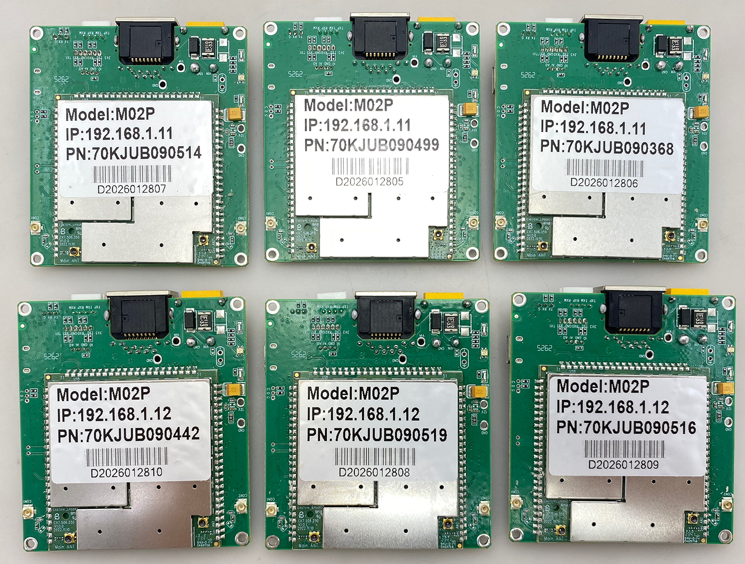
Performance & Range Expectations
-
Without external power amplification, users can expect reliable LOS ranges up to 15-17 km (air-to-ground). With suitable antennas, line of sight, and favorable conditions.
-
Adding a power amplifier (2W, 5W, 10W) can extend range significantly, depending on antenna gain, terrain, and regulatory limits on radiated power.
-
Signal quality, bandwidth, and modulation adapt automatically to environmental conditions to maintain link performance; worse conditions reduce modulation order or bandwidth, but preserve the link rather than dropping.
Configuration & Control
-
Web UI: via the Ethernet or IP network, you can access configuration menus: select frequency band, modulation, bandwidth, frame modes, streaming ratios (video/control), encryption settings, etc.
-
UART / Serial Control: For integration with autopilots / flight controllers, remote firmware updates, in-field adjustments of settings.
-
Switch for external PA: Some models include a mechanism for controlling an external power amplifier (on/off), for instance to save power when full power isn’t needed.
Comparisons / Advantages
What distinguishes the IS1681 from simpler, one-way video transmitters or basic RC control links:
-
Bidirectional data & video rather than just one-way video/telemetry.
-
Support for full network topologies (mesh, relay networks) rather than simple point-to-point only.
-
Multiple frequency options allow adaptation to regulatory and environmental constraints.
-
Transparent IP networking means it can carry arbitrary IP traffic (e.g. video, telemetry, control) rather than being limited to specialized proprietary protocols.
-
Integrated serial/TTL interfaces make it easier to hook up flight controllers, cameras, data loggers without needing many converters.
Technical Specification Summary
| Parameter | Specification |
|---|---|
| Frequency Bands | 800 MHz (806-826 MHz), 1.4 GHz (1428-1448 MHz), 2.4 GHz (2402-2482 MHz) |
| Bandwidth Options | 3 / 5 / 10 / 20 MHz |
| Modulation | QPSK / 16QAM / 64QAM (adaptive) |
| RF Output Power | ~25 ± 2 dBm (default) |
| Sensitivity | ~–106 to –108 dBm for 1 Mbps in supported bands |
| Maximum Data Rate | ~30 Mbps @ 20 MHz bandwidth (shared among nodes) |
| Networking Modes | Point-to-Point, Point-to-Multipoint, Star, Relay/Repeater, Mesh / IP Mesh |
| Interfaces | Dual Ethernet, 3 UART/TTL, Audio I/O, USB for firmware |
| Antennas | Dual antennas: main (TX/RX) + auxiliary (RX only) |
| Power Supply | 7-30 V DC, < ~4.5 W typical |
| Physical Size / Weight | ~58 × 64 × 13 mm; ~32 g |
| Operating Temp. | –20 °C to +65 °C; Storage: –40 °C to +80 °C |
Considerations & Tips
-
Regulatory compliance: When using higher transmit powers or certain frequency bands, ensure that operations are permitted in your area. Licensing, power limits, and band usage differ by country.
-
Antenna setup: To get the advertised range, high-gain antennas, proper mounting (elevated, clear LOS), and matching connectors are essential. Diversity via the auxiliary antenna helps in multipath or blocked signal scenarios.
-
Powering & heat dissipation: Even though module power consumption is modest (~4–5 W), including any PA will add heat. Good airflow / heatsinking is needed especially if enclosed. Use the onboard LED indicators to monitor link quality.
-
Firmware & updates: Keep firmware updated for best performance and bug fixes. Use USB or Web UI as provided.
-
Bandwidth allocation: If using mesh or multiple nodes, bandwidth is shared—so ensure the system design accounts for video + telemetry + control demands, and allocate uplink/downlink ratios as needed.
Conclusion
The UAV Wireless Video Data RC Control Link Module is a versatile, powerful, and robust solution for those wanting more than just simple video: it gives you full two-way communications, networking modes, flexible interfaces, and high performance over long ranges. Whether you’re a developer building custom UAV platforms, a FPV pilot needing reliable long-distance video, or a systems integrator deploying swarm or distributed sensor solutions, this module offers an excellent balance of capability, flexibility, and integration ease.
FAQ
Q: Can I purchase the modem core board separately?
If I can get the separate modem core board, I can introduce a wider range of customized products with different sizes and interfaces based on my clients’ requirements.
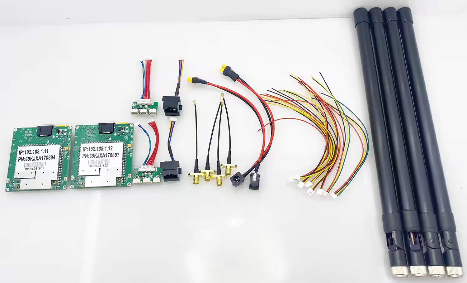
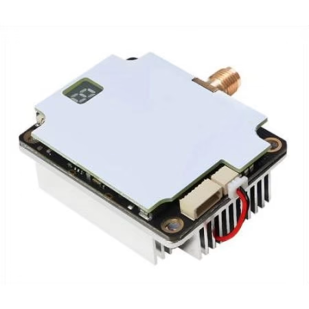
Does your company provide the core board shown in the image separately?
A: Yes, we can provide the modem core board separately for customers who have specific customization requirements. However, based on our experience, using a standalone modem core board to develop a new customized product usually requires additional engineering work. The customer may need to redesign the motherboard (PCB), customize the mechanical structure, define new interfaces, modify the software/UI, and optimize the wireless RF parameters according to the final application requirements.
This type of customization normally requires cooperation between multiple engineering teams, including:
- Hardware engineers for PCB and interface redesign
- Software engineers for firmware, UI, and control software customization
- RF engineers for wireless frequency, power, and performance optimization
For a small quantity project, the development cost and engineering investment can be relatively high. In most cases, we recommend considering this approach when the expected production quantity is around 500 units or more. For lower quantities, using our existing complete wireless video transmission products with minor customization is usually a more cost-effective solution. If you have a specific project requiring a customized size, interface, frequency range, or application solution, please share your requirements. We can evaluate the feasibility and provide the most suitable solution.



Reviews
There are no reviews yet.