
Das System besteht aus sechzehn luftgestützten Datalink Air Units (eine pro Vogel), eine einzelne Datalink-Bodeneinheit, und eine Bodenkontrollstation (GCS). Der Zweck besteht darin, Schnittstellen zu spezifizieren, Kabellängen, Port zählt, und Abnahmetests, damit die von Lieferanten gelieferten Einheiten mit dem bestehenden FCC zusammenarbeiten (Flugsteuerungscomputer), Kameras (Suchende), und das GCS.
Für den Aufbau einer Datenverbindung zwischen a ist eine Komplettlösung erforderlich Bodenstation Und 4 UAV-Lufteinheiten. Das System soll eine zuverlässige Kommunikation ermöglichen, Kontrolle, und Überwachung aller UAVs gleichzeitig. Detaillierte technische Anforderungen finden Sie weiter unten.
Überblick:
∙ Konfiguration: 1 × Bodenkontrolleinheit (AVV) kommunizieren mit 4 × Lufteinheiten (AUs) ∙ Kommunikationstyp: Bidirektionale Punkt-zu-Multipunkt-Verbindung (Ethernet + UART) ∙ Reichweite: ≥ 80 km Sichtlinie (LOS)
∙ Betriebsband: 1.4GHz(L-Band)
∙ Modulationsschema: TDD-OFDM / QPSK / 16-QAM
∙ Leistungsbedarf: Betriebsspannung (12V), Aktueller Schwellenwert (≤2A) ∙ Temperaturbereich: -20°C bis 75 °C
Datendurchsatz und Bandbreite:
| Parameter | Erfordernis | Notizen |
| Videodatenrate (pro Suchender) | 5 – 9 Mbit/s | 1080P @ 30 fps H.264/265-Komprimierung |
| Telemetrie + Kontrolle (gemäß FCC) | 200 – 300 kbit/s | UART-basierte bidirektionale Steuerdaten |
| Aggregierter Videodurchsatz (4 AUs) | 24 – 36 Mbit/s | Kombinierter Video-Uplink |
| Aggregierte Telemetrie/Steuerung | 1 Mbit/s | Vernachlässigbar im Vergleich zu Video |
| Gesamte erforderliche Uplink-Bandbreite | ≥ 36 Mbit/s | Mit 20% FEC + Overhead ≈ 42 Mbit/s |
Latenz- und Qualitätsanforderungen:
| Parameter | Erfordernis | Notizen |
| Bitfehlerrate | < 8×10⁻⁸ | Bei maximaler Reichweite |
| Datenverzögerung | < 1MS | Erforderlich für Echtzeit-Suchbetrieb und Datenübertragung |
| Paketverlust | < 1% | Mit FEC + ARQ-Mechanismen |
| Fehlerkorrektur | FEC + CRC + ARQ | Obligatorisch für die Zuverlässigkeit der Telemetrie |
Budget verknüpfen & HF-Parameter:
| Parameter | Zielwert | Notizen |
| Sendeleistung (Lufteinheit) | 4 – 5 W | – |
| Sendeleistung (Bodeneinheit) | 4 – 5 W | – |
| Antennengewinn (Lufteinheit) | >3dB | Antennenmuster: Isotrop |
| Antennengewinn (Bodeneinheit) | 12 – 18 dB | Richtantenne |
| Empfängerempfindlichkeit | –103 dBm bei 10 MHz | Für 10⁻⁵ BER |
| Link-Marge @ 80 km | > 10 dB | Sorgt für robustes Video + Datenverbindung |
NOTIZ:
⮚ Für eine nahtlose Integration zwischen dem CUAV V5+ Flugcontroller und externen Peripheriegeräten, Es ist wichtig, dass der UART-Webstuhl a aufrechterhält Direkter und unkomplizierter Verkabelungsaufbau. Speziell, Der Webstuhl vom UART-Port sollte als ausgelegt sein eine einzige geradlinige Verbindung ohne die Einführung zusätzlicher Konverter oder Zwischenplatinen. Dies minimiert potenzielle Fehlerquellen, reduziert die Latenz, und sorgt für eine leichte und zuverlässige Verkabelungsarchitektur.
⮚ Darüber hinaus, Der Webstuhl muss mit Transistor-Transistor-Logik arbeiten (TTL) Spannungsniveaus, da der V5+ Flugcontroller über TTL UART kommuniziert. Jede Abweichung von TTL (wie RS-232- oder RS-485-Pegel) würde externe Pegelumsetzer oder Konverter erfordern, was der Forderung nach einem direkten Webstuhl widerspricht. Durch Einhaltung der TTL-Standards, Die Signalkompatibilität bleibt erhalten, sicherzustellen:
o Direkte Kommunikation zwischen V5+ und angeschlossenen Modulen.
o Reduzierte Hardware-Komplexität durch Eliminierung von Konvertern oder Übersetzern. o Geringeres Gewicht und verbesserte Zuverlässigkeit, da weniger Komponenten am Signalweg beteiligt sind.
o Verbesserte Signalintegrität, da zusätzliche Konvertierungsstufen zu Rauschen oder Timing-Fehlanpassungen führen können.
Abschließend, Das Kabelbaumdesign sollte unbedingt einen direkten UART-Kabelbaum bieten, der mit TTL-Spannungen betrieben wird, Es entspricht den elektrischen Spezifikationen des CUAV V5+ und garantiert optimale Leistung bei Anwendungen in der Luft.
Systemübersicht:
Systembeschreibung auf hoher Ebene:
1. Vier UAVs, jeweils ausgestattet mit:
O 1 × Datalink-Lufteinheit
O 1 × FCC (Flugkontrollcomputer, z.B., FALSCH V5+)
O 1 × Sucher / Kamera
2. 1 × Datalink-Bodeneinheit, verbunden mit der Bodenkontrollstation (GCS).
Datenfluss (Überblick): Video- und Sensordaten von jeder Kamera werden über den Ethernet-Anschluss der Kamera an die zugehörige Datalink Air Unit weitergeleitet. Telemetrie- und Steuerdaten zwischen der FCC und der Air Unit werden über eine UART-Verbindung übertragen. Die Datalink Air Unit überträgt diese Streams über die Datenverbindung an die Bodeneinheit; Die Ground Unit demultiplext die Streams und präsentiert sie dem GCS als einen einzelnen Ethernet-Stream (Kameravideos und Daten) und eine einzelne Serie (UART/USB) Telemetrie-Stream.
Anforderungen an die Lufteinheit:
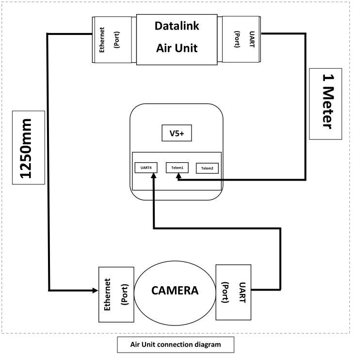
Jede Datalink-Lufteinheit (eine pro UAV) muss die folgenden verbindlichen Anforderungen erfüllen:
1. Schnittstellen & Häfen (Minimum):
O 1 × UART-Port (Minimum). Dieser Port wird für die Telemetrie-/Steuerungsverbindung zum FCC verwendet (Telemetrie-Ports Telem1 / Telem2 auf der FCC).
O 1 × Ethernet-Anschluss (Minimum). Dieser Port wird zum Empfang von Kamera-/Sucher-Ethernet-Daten verwendet.
2. Kabelverbindung (Lieferung mit der Air Unit):
O 1 × UART-Kabel (primär) - Länge: 1.0 M (±5 %). Das Kabel muss TX tragen, RX, GND und VCC. Das Kabel muss so terminiert sein, dass es an einem Ende mit dem Datalink-UART-Anschluss und am anderen Ende mit dem FCC-Telemetrieanschluss übereinstimmt.
O 1 × Ethernet-Kabel (primär) - Länge: 1.0 M (±5 %). Das Kabel muss ein geschirmtes Standard-Cat5e- oder Cat6-Patchkabel mit RJ45-Anschlüssen sein.
O 2 × Ersatzsätze (pro Lufteinheit) – d.h., Mit jeder Lufteinheit werden zwei zusätzliche UART-Kabel und zwei zusätzliche Ethernet-Kabel mitgeliefert (Insgesamt pro Einheit geliefert = 3 UART-Kabel, 3 Ethernet-Kabel).
3. Mechanisch & Körperlich:
o Kabel sollten farblich gekennzeichnet sein (empfohlen) und verfügen über klare Richtungsmarkierungen, wenn die Pinbelegung nicht symmetrisch ist.
4. Elektrik/Protokoll:
O UART: Unterstützt gängige Baudraten bis mindestens 921600 bps. Stellen Sie vom Benutzer konfigurierbare UART-Parameter bereit.
O Ethernet: Zumindest unterstützen 100 Mbit/s-Betrieb (Gigabit bevorzugt). Unterstützt gängige Transportprotokolle (UDP, RTSP für Video und UDP zur Steuerung) — Die spezifische Protokollauswahl muss konfigurierbar sein.
Anforderungen an die Bodeneinheit:
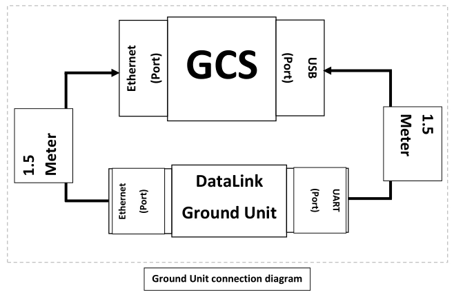
Die Bodeneinheit führt die Demultiplexierung der Daten aller vier Lufteinheiten durch und stellt eine einheitliche Schnittstelle zum GCS dar. Zwingende Anforderungen sind:
1. Schnittstellen & Häfen (Minimum):
O 1 × UART-Port (dem GCS vorgelegt). Die Bodeneinheit soll Telemetrieströme von allen vier Lufteinheiten sammeln und sie dem GCS als eine einzige UART/USB-Schnittstelle präsentieren (z.B., Der UART der Bodeneinheit ist mit einer USB-Schnittstelle am GCS verbunden).
O 1 × Ethernet-Anschluss (dem GCS vorgelegt). Die Bodeneinheit soll Kamera-/Video- und Datenströme von den vier Lufteinheiten bündeln und sie dem GCS als eine einzige Ethernet-Schnittstelle präsentieren.
2. Aggregationsverhalten:
o Die Bodeneinheit muss vier unabhängige eingehende Datenströme akzeptieren (eine von jeder Lufteinheit) und demultiplexen sie in einen kombinierten Ethernet-Stream und einen kombinierten seriellen Stream. Aus dem GCS’ Perspektivisch soll es nur eine Ethernet-Verbindung und eine UART-Verbindung geben, die konfiguriert und überwacht werden müssen.
o Bei der Aggregation muss die Quelladressierung erhalten bleiben, So kann das GCS erkennen, welcher Stream von welchem Bird stammt. Die Bodeneinheit darf keine Identifikationsinformationen pro Vogel verlieren.
3. Kabelverbindung (Wird mit der Bodeneinheit geliefert):
O 1 × UART-Kabel (primär) - Länge: 400 mm (0.4 M). Das Kabel muss eine Verbindung vom UART-Port der Bodeneinheit zum GCS-USB-Port ermöglichen (wenn der UART der Bodeneinheit ein direkter UART ist, Stellen Sie ein USB-UART-Adapterkabel bereit). Das Kabel muss TX tragen, RX, GND und VCC.
O 1 × Ethernet-Kabel (primär) - Länge: 400 mm (0.4 M). Das Kabel muss ein abgeschirmtes Cat5e/Cat6-Patchkabel mit RJ45-Anschlüssen sein.
O 2 × Ersatzsätze – zwei zusätzliche UART- und zwei zusätzliche Ethernet-Kabel, die als Ersatzteile mit der Bodeneinheit geliefert werden.
4. Elektrik/Protokoll:
o Die Aggregation muss in Bezug auf Ethernet-Frames für Video transparent sein; Bei Bedarf kann die Bodeneinheit die Ströme in einen einzigen Transportstrom umpacken, muss jedoch die Zeitinformationen und die Quellenidentifizierung pro Vogel beibehalten.
O Telemetrie-Multiplexing: Die Bodeneinheit soll Telemetrieströme zeitmultiplexen oder paketieren und in einen einzigen UART-Strom mit klarem Rahmen und optionalen Tags bündeln, um Nachrichten anhand der Vogel-ID zu unterscheiden. Das zum Multiplexen verwendete Protokoll muss dokumentiert sein und von der GCS-Software unterstützt werden.
Konnektivität & Kabelspezifikationen
In diesem Abschnitt werden die empfohlenen Kabel- und Steckerspezifikationen aufgeführt, um eine zuverlässige Leistung in Luft- und Bodenumgebungen zu gewährleisten.
1. Ethernet-Kabel (Lufteinheit -> Kamera- und Bodeneinheit -> GCS): Standardmäßig abgeschirmte Cat5e- oder Cat6-Patchkabel mit RJ45-Anschlüssen. Vollständig abgeschirmt verwenden (STP) Kabel, wenn die Installation hohe elektromagnetische Störungen aufweist.
2. Ethernet-Länge (Lufteinheit): 1.0 m ±5 %.
3. Ethernet-Länge (Bodeneinheit): 400 mm ±5%.
4. UART-Kabel (Lufteinheit -> FCC-Telemetrie): 4-Leiterkabel (TX, RX, GND, optionales RTS/CTS). Länge: 1.0 m ±5 %.
5. UART-Kabel (Bodeneinheit -> GCS USB/UART): 400 mm ±5% (Schließen Sie einen USB-UART-Adapter ein, falls dies vom GCS gefordert wird).
6. Kabelschirmung und Erdung: Sorgen Sie für eine gemeinsame Erdung und stellen Sie sicher, dass die Abschirmung gemäß bewährter Vorgehensweise an einem Ende abgeschlossen wird, um Erdschleifen zu vermeiden. Wenn mit Vibrationen zu rechnen ist, verwenden Sie verriegelbare RJ45- oder einrastende Steckverbinder.
7. Stellen Sie Adapterkabel für die Verbindung von Datalink UART mit CUAV V5+-Telemetrieanschlüssen bereit (wenn die Datalink-Einheit keinen nativ kompatiblen Anschluss bereitstellt).
8. Wo die Kamera Power-over-Ethernet unterstützt (PoE) aber die Datalink Air Unit liefert kein PoE, Stellen Sie einen PoE-Injektor bereit.
Funktional & Protokollanforderungen
Wichtige funktionale Anforderungen und Empfehlungen:
1. Identifizierung pro Vogel: Jeder Datenstrom (Video oder Telemetrie) MUSS mit einer eindeutigen Vogel-ID gekennzeichnet sein, damit das GCS Streams Fahrzeugen zuordnen kann.
2. Multiplexing-Schema: Die Bodeneinheit muss ein deterministisches Multiplexschema für die Telemetrie implementieren (UART) Dadurch kann GCS Nachrichten anhand der Bird-ID analysieren und weiterleiten. 3. Latenz und Durchsatz: Das System soll die zusätzliche Aggregationslatenz minimieren. 4. Zuverlässigkeit: Die Bodeneinheit muss den vorübergehenden Verlust einer oder mehrerer Lufteinheiten ordnungsgemäß bewältigen und die verbleibenden Ströme weiterhin an das GCS weiterleiten.
5. Konfigurationsschnittstelle: Geben Sie eine Konfigurationsmethode an (ein ausführliches Dokument) um Vogel-IDs festzulegen, UART-Baudraten, und Prioritäten pro Stream.
Eine Frage stellen
Vielen Dank für deine Antwort. ✨