
В состав системы входят шестнадцать бортовых воздушных блоков линии передачи данных. (один на птицу), один наземный блок канала передачи данных, и наземная станция управления (ГКС). Цель состоит в том, чтобы указать интерфейсы, длина кабеля, количество портов, и приемочные испытания, чтобы устройства, поставляемые поставщиками, могли взаимодействовать с существующими стандартами FCC. (компьютер управления полетом), камеры (искатели), и ГКС.
Требуется комплексное решение для установления канала передачи данных между наземная станция и 4 авиационные подразделения БПЛА. Система должна обеспечивать надежную связь, контроль, и мониторинг всех БПЛА одновременно. Подробные технические требования представлены ниже.
Обзор:
∙ Конфигурация: 1 × Наземный блок управления (ГКУ) общение с 4 × Воздушные юниты (Из) ∙ Тип связи: Двунаправленная связь «точка-многоточка» (Ethernet + УАРТ) ∙ Диапазон: ≥ 80 км прямой видимости (ЛОС)
∙ Рабочий диапазон: 1.4ГГц(L-диапазон)
∙ Схема модуляции: TDD-OFDM / КФСК / 16-КАМ
∙ Требования к питанию: рабочее напряжение (12В), Текущий порог (≤2А) ∙ Температурный диапазон: -20от °С до 75 °С
Пропускная способность и пропускная способность данных:
| Параметр | Требование | Примечания |
| Скорость видеоданных (на каждого искателя) | 5 – 9 Мбит/с | 1080п@ 30 кадр/с, сжатие H.264/265 |
| Телеметрия + Контроль (согласно FCC) | 200 – 300 кбит/с | Двунаправленные управляющие данные на основе UART |
| Совокупная пропускная способность видео (4 Из) | 24 – 36 Мбит/с | Комбинированный видеоканал |
| Совокупная телеметрия/управление | 1 Мбит/с | Незначительно по сравнению с видео |
| Общая необходимая пропускная способность восходящей линии связи | ≥ 36 Мбит/с | С 20% ТЭК + накладные расходы ≈ 42 Мбит/с |
Задержка и требования к качеству:
| Параметр | Требование | Примечания |
| Частота битовых ошибок | < 8×10⁻⁸ | На максимальной дальности |
| Задержка данных | < 1РС | Требуется для работы ГСН в реальном времени и передачи данных. |
| Потеря пакетов | < 1% | С ФЭК + Механизмы ARQ |
| Исправление ошибок | ТЭК + Контрольная сумма + ARQ | Обязательно для надежности телеметрии |
Ссылка на бюджет & РЧ параметры:
| Параметр | Целевое значение | Примечания |
| Мощность передачи (Воздушный блок) | 4 – 5 Вт | – |
| Мощность передачи (Наземное подразделение) | 4 – 5 Вт | – |
| Усиление антенны (Воздушный блок) | >3дБ | Диаграмма направленности антенны: изотропный |
| Усиление антенны (Наземное подразделение) | 12 – 18 дБ | Направленная антенна |
| Чувствительность приемника | –103 дБм @ 10 МГц | За 10⁻⁵ BER |
| Поле ссылки @ 80 км | > 10 дБ | Обеспечивает надежное видео + канал передачи данных |
ПРИМЕЧАНИЕ:
⮚ Для плавной интеграции между полетным контроллером CUAV V5+ и внешними периферийными устройствами., важно, чтобы схема UART поддерживала прямая и несложная структура проводки. Конкретно, шлейф от порта UART должен быть спроектирован как одно прямое соединение без применения дополнительных преобразователей или промежуточных плат. Это сводит к минимуму потенциальные точки отказа., уменьшает задержку, и обеспечивает легкую и надежную архитектуру проводки.
⮚ Кроме того, станок должен работать на транзисторно-транзисторной логике (ТТЛ) уровни напряжения, поскольку полетный контроллер V5+ обменивается данными через TTL UART. Любое отклонение от TTL (например уровни RS-232 или RS-485) потребуются внешние преобразователи уровня или преобразователи., что противоречит требованию прямого ткацкого станка. Соблюдая стандарты TTL, совместимость сигналов сохраняется, обеспечение:
o Прямая связь между V5+ и подключенными модулями.
o Снижение сложности аппаратного обеспечения за счет исключения преобразователей и трансляторов.. o Меньший вес и повышенная надежность., поскольку в тракте сигнала участвует меньше компонентов.
o Улучшенная целостность сигнала, поскольку дополнительные этапы преобразования могут привести к появлению шума или несоответствию времени.
В заключение, конструкция жгута должна строго предусматривать сквозной жгут проводов UART, работающий при напряжениях TTL, соответствие электрическим характеристикам CUAV V5+ и гарантия оптимальной производительности при использовании в воздухе..
Обзор системы:
Общее описание системы:
1. Четыре БПЛА, каждый оснащен:
о 1 × Воздушный блок линии передачи данных
о 1 × ФКС (Компьютер управления полетом, например, ЛОЖЬ V5+)
о 1 × Искатель / Камера
2. 1 × Наземный блок линии передачи данных, подключенный к наземной станции управления (ГКС).
Поток данных (обзор): Данные видео и датчиков с каждой камеры передаются на соответствующий воздушный блок Datalink через порт Ethernet камеры.. Данные телеметрии и управления между FCC и воздушным блоком передаются по каналу UART.. Воздушный блок линии передачи данных передает эти потоки по каналу передачи данных на наземный блок.; наземный модуль демультиплексирует потоки и представляет их GCS как один поток Ethernet (видео и данные камеры) и один сериал (УАПП/USB) поток телеметрии.
Требования к воздушному блоку:
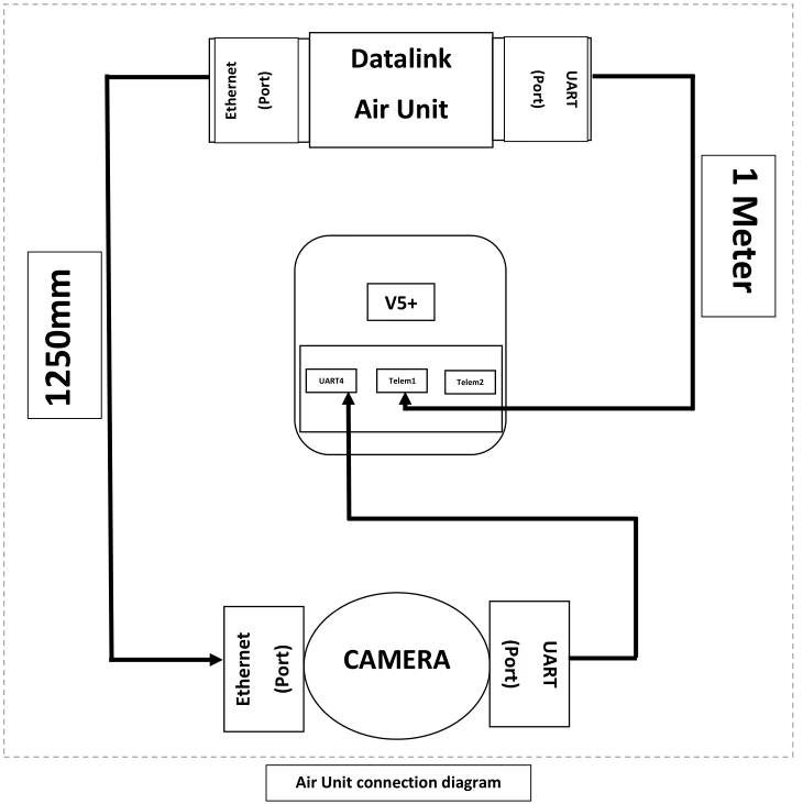
Каждый воздушный блок канала передачи данных (один на БПЛА) должен отвечать следующим обязательным требованиям:
1. Интерфейсы & Порты (минимум):
о 1 × UART-порт (минимум). Этот порт должен использоваться для подключения телеметрии/управления к FCC. (порты телеметрии Телем1 / Телем2 на FCC).
о 1 × Порт Ethernet (минимум). Этот порт будет использоваться для получения данных Ethernet камеры/искателя.
2. Кабельное соединение (поставляется с воздушным блоком):
о 1 × UART-кабель (начальный) - длина: 1.0 м (±5%). Кабель должен передавать TX, прием, Земля и VCC. Кабель должен быть оконцован так, чтобы он совпадал с разъемом Datalink UART на одном конце и телеметрическим разъемом FCC на другом.
о 1 × Ethernet-кабель (начальный) - длина: 1.0 м (±5%). Кабель должен представлять собой стандартный экранированный патч-кабель Cat5e или Cat6 с разъемами RJ45.
о 2 × запасные комплекты (за воздушный блок) - т.е., Два дополнительных кабеля UART и два дополнительных кабеля Ethernet должны поставляться с каждым воздушным блоком. (общее количество в комплекте = 3 кабеля UART, 3 Ethernet-кабели).
3. Механический & Физический:
o Кабели должны иметь цветовую маркировку. (рекомендуется) и иметь четкую маркировку направления, если выводы несимметричны.
4. Электрика/Протокол:
о УАРТ: Поддержка общих скоростей передачи данных, по крайней мере, до 921600 б/с. Предоставление настраиваемых пользователем параметров UART.
о Ethernet: Поддержите хотя бы 100 Операция Мбит/с (Гигабитный предпочтительно). Поддержка общих транспортных протоколов (UDP, RTSP для видео и UDP для управления) — выбор конкретного протокола должен быть конфигурируемым.
Требования к наземному блоку:
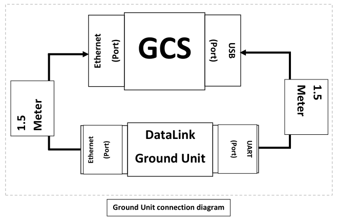
Наземный блок выполняет демультиплексирование данных от всех четырех воздушных блоков и предоставляет единый интерфейс для GCS.. Обязательные требования::
1. Интерфейсы & Порты (минимум):
о 1 × UART-порт (представлено GCS). Наземный модуль объединяет потоки телеметрии со всех четырех воздушных блоков и представляет их в GCS как единый интерфейс UART/USB. (например, UART наземного устройства, подключенный к интерфейсу USB на GCS).
о 1 × Порт Ethernet (представлено GCS). Наземный модуль объединяет потоки камер/видео и данных от четырех воздушных блоков и представляет их как единый интерфейс Ethernet для GCS.
2. Поведение агрегирования:
o Наземный блок должен принимать четыре независимых входящих потока данных. (по одному от каждой авиачасти) и демультиплексировать их в объединенный поток Ethernet и объединенный последовательный поток. Из ГКС’ В перспективе для настройки и мониторинга должен быть только один канал Ethernet и один канал UART.
o Агрегация должна сохранять адресацию источника., чтобы GCS мог определить, какой поток от какой Bird. Наземный блок не должен терять идентификационную информацию по каждой птице.
3. Кабельное соединение (поставляется с наземным блоком):
о 1 × UART-кабель (начальный) - длина: 400 мм (0.4 м). Кабель должен обеспечивать подключение порта UART наземного устройства к порту USB GCS. (если UART наземного блока является прямым UART, предоставьте переходной кабель USB-UART). Кабель должен передавать TX, прием, GND и VCC.
о 1 × Ethernet-кабель (начальный) - длина: 400 мм (0.4 м). Кабель должен быть экранированным патч-кабелем Cat5e/Cat6 с разъемами RJ45.
о 2 × запасные комплекты — два дополнительных кабеля UART и два дополнительных кабеля Ethernet, поставляемые в качестве запасных частей с наземным модулем.
4. Электрика/Протокол:
o Агрегация должна быть прозрачной по отношению к кадрам Ethernet для видео.; при необходимости наземный модуль может переупаковать потоки в один транспортный поток, но должен сохранить информацию о синхронизации и идентификацию источника для каждой птицы.
о Мультиплексирование телеметрии: Наземный блок должен мультиплексировать по времени или пакетировать потоки телеметрии в единый поток UART с четким кадрированием и дополнительными тегами для различения сообщений по идентификатору птицы.. Протокол, используемый для мультиплексирования, должен быть задокументирован и поддерживаться программным обеспечением GCS..
Возможности подключения & Характеристики кабеля
В этом разделе перечислены рекомендуемые характеристики кабелей и разъемов, обеспечивающие надежную работу в воздушной и наземной среде.
1. Ethernet-кабели (Воздушная часть -> Камера и наземный блок -> ГКС): Стандартные экранированные патч-кабели Cat5e или Cat6 с разъемами RJ45.. Используйте полностью экранированный (СТП) кабель, если установка имеет высокие электромагнитные помехи.
2. Длина Ethernet (Воздушный блок): 1.0 м ±5%.
3. Длина Ethernet (Наземное подразделение): 400 мм ±5%.
4. UART-кабели (Воздушная часть -> телеметрия ФКС): 4-проводящий кабель (Техас, прием, Земля, опционально RTS/CTS). Длина: 1.0 м ±5%.
5. UART-кабель (Наземное подразделение -> ГКС USB/UART): 400 мм ±5% (включите адаптер USB-UART, если этого требует GCS).
6. Экранирование и заземление кабеля: Обеспечьте общее заземление и убедитесь, что экранирование завершено на одном конце в соответствии с рекомендациями, чтобы избежать контуров заземления.. Если ожидается вибрация, используйте фиксирующиеся разъемы RJ45 или защелкивающиеся разъемы.
7. Предоставьте переходные кабели для подключения Datalink UART к телеметрическим разъемам CUAV V5+. (если блок Datalink изначально не имеет совместимого разъема).
8. Где камера поддерживает Power-over-Ethernet (PoE) но воздушный блок Datalink не обеспечивает PoE, предоставьте PoE-инжектор.
Функциональный & Требования протокола
Ключевые функциональные требования и рекомендации:
1. Идентификация по птицам: Каждый поток данных (видео или телеметрия) ДОЛЖЕН быть помечен уникальным идентификатором птицы, чтобы GCS мог сопоставлять потоки с транспортными средствами.
2. Схема мультиплексирования: Наземный блок должен реализовать детерминированную схему мультиплексирования телеметрических данных. (УАРТ) позволяя GCS анализировать и маршрутизировать сообщения по Bird ID. 3. Задержка и пропускная способность: Система должна минимизировать дополнительную задержку агрегации. 4. Надежность: Наземный блок должен корректно обрабатывать временную потерю одного или нескольких воздушных блоков и продолжать передавать оставшиеся потоки в GCS.
5. Интерфейс конфигурации: Предоставьте метод настройки (подробный документ) установить идентификаторы птиц, Скорость передачи данных UART, и приоритеты для каждого потока.
Задать вопрос
Спасибо за ответ. ✨