
Le système comprend seize unités aériennes Datalink aéroportées (un par oiseau), a single Datalink Ground Unit, et une station de contrôle au sol (CGC). Le but est de spécifier les interfaces, longueurs de câble, port counts, and acceptance tests so that units delivered by suppliers will interoperate with the existing FCC (ordinateur de contrôle de vol), caméras (chercheurs), and the GCS.
Une solution complète est nécessaire pour établir une liaison de données entre un ground station et 4 UAV air units. Le système doit permettre une communication fiable, contrôle, and monitoring of all UAVs simultaneously. Detailed technical requirements are provided below.
Aperçu:
∙ Configuration: 1 × Unité de contrôle au sol (CGU) communiquer avec 4 × Unités aériennes (De) ∙ Type de communication: Liaison bidirectionnelle point à multipoint (Ethernet + UART) ∙ Gamme: ≥ 80 km de visibilité directe (LDV)
∙ Bande de fonctionnement: 1.4GHz(Bande L)
∙ Schéma de modulation: TDD-OFDM / QPSK / 16-MAQ
∙ Exigence de puissance: tension de fonctionnement (12V), Seuil actuel (≤2A) ∙ Plage de température: -20°C à 75°C
Débit de données et bande passante:
| Paramètre | Exigence | Remarques |
| Débit de données vidéo (par chercheur) | 5 – 9 Mbit/s | 1080p@ 30 fps H.264/265 compression |
| Télémétrie + Contrôle (par FCC) | 200 – 300 kbps | Données de contrôle bidirectionnel basées sur UART |
| Débit vidéo global (4 De) | 24 – 36 Mbit/s | Liaison montante vidéo combinée |
| Télémétrie/Contrôle agrégé | 1 Mbit/s | Négligeable par rapport à la vidéo |
| Bande passante totale requise pour la liaison montante | ≥ 36 Mbit/s | Avec 20% FEC + frais généraux ≈ 42 Mbit/s |
Exigences de latence et de qualité:
| Paramètre | Exigence | Remarques |
| Taux d'erreur sur les bits | < 8×10⁻⁸ | À portée maximale |
| Retard de données | < 1MS | Required for real-time seeker operation and data transmission |
| Perte de paquets | < 1% | Avec FEC + Mécanismes ARQ |
| Correction d'erreur | FEC + CRC + ARQ | Obligatoire pour la fiabilité de la télémétrie |
Budget des liens & Paramètres RF:
| Paramètre | Target Value | Remarques |
| Puissance de transmission (Unité aérienne) | 4 – 5 W | – |
| Puissance de transmission (Unité au sol) | 4 – 5 W | – |
| Gain d'antenne (Unité aérienne) | >3dB | Modèle d'antenne: Isotrope |
| Gain d'antenne (Unité au sol) | 12 – 18 dB | Antenne directionnelle |
| Sensibilité du récepteur | –103dBm @ 10 MHz | Pour 10⁻⁵ BER |
| Marge du lien @ 80 kilomètres | > 10 dB | Garantit une vidéo robuste + liaison de données |
NOTE:
⮚ For seamless integration between the CUAV V5+ flight controller and external peripherals, il est essentiel que le métier à tisser UART maintienne un direct and uncomplicated wiring structure. Spécifiquement, le métier à tisser du port UART doit être conçu comme un single straight line connection without introducing any additional converters or intermediary boards. Cela minimise les points de défaillance potentiels, réduit la latence, and ensures a lightweight and reliable wiring architecture.
⮚ Furthermore, le métier à tisser doit fonctionner selon la logique transistor-transistor (Durée de vie) voltage levels, car le contrôleur de vol V5+ communique via TTL UART. Tout écart par rapport au TTL (tels que les niveaux RS-232 ou RS-485) would necessitate external level shifters or converters, ce qui contredit l'exigence d'un métier à tisser direct. By adhering to TTL standards, la compatibilité du signal est maintenue, assurer:
o Direct communication between the V5+ and connected modules.
o Reduced hardware complexity by eliminating converters or translators. o Lower weight and improved reliability, as fewer components are involved in the signal path.
o Improved signal integrity, since additional conversion stages can introduce noise or timing mismatches.
En conclusion, the loom design should strictly provide a straight-through UART wiring harness operating at TTL voltages, aligning with the CUAV V5+ electrical specifications and guaranteeing optimal performance in airborne applications.
Présentation du système:
Description du système de haut niveau:
1. Quatre drones, chacun équipé de:
o 1 × Unité aérienne Datalink
o 1 × FCC (Ordinateur de contrôle de vol, par ex., FAUX V5+)
o 1 × Chercheur / Caméra
2. 1 × Unité au sol Datalink connectée à la station de contrôle au sol (CGC).
Flux de données (aperçu): Video and sensor data from each camera is provided to its associated Datalink Air Unit via the camera’s Ethernet port. Telemetry and control data between the FCC and the Air Unit is carried over a UART link. The Datalink Air Unit transmits these streams over the data link to the Ground Unit; the Ground Unit demultiplexes the streams and presents them to the GCS as a single Ethernet stream (vidéo et données de la caméra) et une seule série (UART/USB) telemetry stream.
Exigences relatives aux unités aériennes:
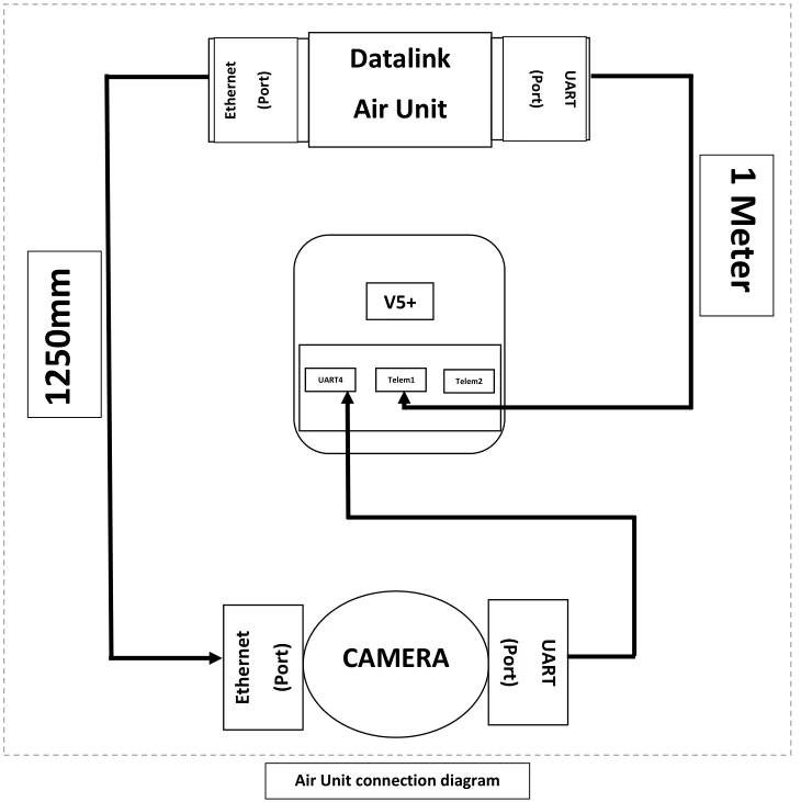
Chaque unité aérienne Datalink (un par drone) doit répondre aux exigences obligatoires suivantes:
1. Interfaces & Ports (minimum):
o 1 ×Port UART (minimum). This port shall be used for telemetry/control connectivity to the FCC (ports de télémétrie Telem1 / Telem2 sur le FCC).
o 1 ×Port Ethernet (minimum). This port shall be used to receive camera/seeker Ethernet data.
2. Connectivité par câble (delivered with the Air Unit):
o 1 × câble UART (primaire) - longueur: 1.0 m (±5%). Le câble doit transporter TX, RX, GND and VCC. Cable must be terminated to match the Datalink UART connector on one end and the FCC telemetry connector on the other.
o 1 × Câble Ethernet (primaire) - longueur: 1.0 m (±5%). Cable shall be standard shielded Cat5e or Cat6 patch cable with RJ45 connectors.
o 2 × jeux de rechange (par unité aérienne) - c'est-à-dire, two additional UART cables and two additional Ethernet cables shall be supplied with each Air Unit (total supplied per unit = 3 UART cables, 3 Câbles Ethernet).
3. Mécanique & Physique:
o Cables should be color-coded (recommandé) and have clear directionality markings if pinouts are not symmetric.
4. Electrical/Protocol:
o UART: Prend en charge les débits en bauds courants jusqu'à au moins 921600 bps. Provide user configurable UART parameters.
o Ethernet: Soutenir au moins 100 Fonctionnement Mbit/s (Gigabit préféré). Support common transport protocols (UDP, RTSP pour la vidéo et UDP pour le contrôle) — specific protocol selection shall be configurable.
Exigences relatives aux unités au sol:
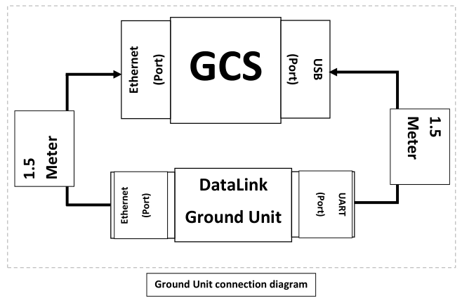
The Ground Unit performs demultiplexing of data from all four Air Units and presents a unified interface to the GCS. Les exigences obligatoires sont:
1. Interfaces & Ports (minimum):
o 1 ×Port UART (présenté au GCS). The Ground Unit shall aggregate telemetry streams from all four air units and present them to the GCS as a single UART/USB interface (par ex., l'unité au sol UART connectée à une interface USB sur le GCS).
o 1 ×Port Ethernet (présenté au GCS). The Ground Unit shall aggregate camera/video and data streams from the four air units and present them as a single Ethernet interface to the GCS.
2. Comportement d'agrégation:
o The Ground Unit shall accept four independent incoming data streams (one from each Air Unit) and demultiplex them to a combined Ethernet stream and a combined serial stream. Du GCS’ perspective there shall be only one Ethernet link and one UART link to configure and monitor.
o Aggregation must preserve source addressing, so the GCS can identify which stream is from which Bird. The Ground Unit shall not lose per-bird identification information.
3. Connectivité par câble (livré avec l'Unité Sol):
o 1 × câble UART (primaire) - longueur: 400 mm (0.4 m). Cable shall allow connection from the Ground Unit UART port to the GCS USB port (if the Ground Unit UART is a direct UART, fournir un câble adaptateur USB-UART). The cable must carry TX, RX, GND and VCC.
o 1 × Câble Ethernet (primaire) - longueur: 400 mm (0.4 m). Cable shall be shielded Cat5e/Cat6 patch cable with RJ45 connectors.
o 2 × spare sets — two additional UART and two additional Ethernet cables supplied as spares with the Ground Unit.
4. Electrical/Protocol:
o Aggregation shall be transparent with respect to Ethernet frames for video; where needed the Ground Unit may repackage streams into a single transport stream but must preserve timing information and per-bird source identification.
o Multiplexage de télémétrie: The Ground Unit shall time-multiplex or packetize telemetry streams into a single UART stream with clear framing and optional tags to distinguish messages by bird ID. The protocol used for multiplexing must be documented and supported by the GCS software.
Connectivité & Spécifications du câble
This section lists the recommended cable and connector specifications to ensure reliable performance in the airborne and ground environments.
1. Câbles Ethernet (Unité aérienne -> Caméra et unité au sol -> CGC): Standard shielded Cat5e or Cat6 patch cables with RJ45 terminations. Utilisation entièrement blindée (STP) cable if the installation has high EMI.
2. Ethernet length (Unité aérienne): 1.0 m ±5%.
3. Ethernet length (Unité au sol): 400 mm ±5%.
4. Câbles UART (Unité aérienne -> Télémétrie FCC): 4-câble conducteur (Émission, RX, GND, RTS/CTS en option). Longueur: 1.0 m ±5%.
5. UART cable (Ground Unit -> GCS USB/UART): 400 mm ±5% (include USB-UART adapter if required by the GCS).
6. Blindage et mise à la terre des câbles: Provide common ground and ensure shielding is terminated at one end per best-practice to avoid ground loops. Use locking RJ45 or latching connectors if vibration is expected.
7. Fournir des câbles adaptateurs pour interfacer Datalink UART aux connecteurs de télémétrie CUAV V5+ (si l'unité Datalink n'expose pas nativement un connecteur compatible).
8. Où la caméra prend en charge Power-over-Ethernet (PoE) but the Datalink Air Unit does not supply PoE, provide a PoE injector.
Fonctionnel & Exigences du protocole
Exigences fonctionnelles clés et recommandations:
1. Identification par oiseau: Chaque flux de données (vidéo ou télémétrie) MUST be tagged with a unique Bird ID so the GCS can map streams to vehicles.
2. Multiplexing Scheme: The Ground Unit shall implement a deterministic multiplexing scheme for telemetry (UART) allowing GCS to parse and route messages by Bird ID. 3. Latency and Throughput: The system shall minimize additional aggregation latency. 4. Fiabilité: Ground Unit must handle temporary loss of one or more air units gracefully and continue to present remaining streams to the GCS.
5. Interface de configuration: Fournir une méthode de configuration (un document détaillé) to set Bird IDs, Débits en bauds UART, et priorités par flux.
Poser une question
Merci pour votre réponse. ✨