System składa się z szesnastu pokładowych jednostek powietrznych Datalink (po jednym na ptaka), pojedynczą jednostkę naziemną łącza danych, oraz naziemna stacja kontroli (GCS). Celem jest określenie interfejsów, długości kabli, liczy się port, i testy akceptacyjne, tak aby jednostki dostarczone przez dostawców współpracowały z istniejącą FCC (komputer sterujący lotem), kamery (poszukiwacze), i GCS.
Do ustanowienia łącza danych pomiędzy a stacja naziemna i 4 Jednostki powietrzne UAV. System powinien umożliwiać niezawodną komunikację, kontrola, i monitorowanie wszystkich UAV jednocześnie. Poniżej znajdują się szczegółowe wymagania techniczne.
Przegląd:
∙ Konfiguracja: 1 × Naziemna jednostka sterująca (GCU) komunikować się z 4 × Jednostki Powietrzne (Z) ∙ Typ komunikacji: Dwukierunkowe łącze punkt-wielopunkt (Ethernet + UART) ∙ Zasięg: ≥ 80 km w zasięgu wzroku (TEN)
∙ Zespół operacyjny: 1.4GHz(Pasmo L)
∙ Schemat modulacji: TDD-OFDM / QPSK / 16-QAM
∙ Zapotrzebowanie na moc: napięcie robocze (12V.), Aktualny próg (≤2A) ∙ Zakres temperatur: -20°C do 75°C
Przepustowość i przepustowość danych:
| Parametr | Wymóg | Notatki |
| Szybkość transmisji danych wideo (na poszukiwacza) | 5 - - 9 Mbps | 1080P @ 30 fps Kompresja H.264/265 |
| Telemetria + Kontrola (według FCC) | 200 - - 300 kb / s | Dwukierunkowe dane sterujące oparte na UART |
| Łączna przepustowość wideo (4 Z) | 24 - - 36 Mbps | Połączone łącze przesyłania wideo |
| Łączna telemetria/sterowanie | 1 Mbps | Znikome w porównaniu do wideo |
| Całkowita wymagana przepustowość łącza zwrotnego | ≥ 36 Mbps | Z 20% FEC + nad głową ≈ 42 Mbps |
Wymagania dotyczące opóźnień i jakości:
| Parametr | Wymóg | Notatki |
| Bitowa stopa błędu | < 8×10⁻⁸ | Przy maksymalnym zasięgu |
| Opóźnienie danych | < 1SM | Wymagane do działania wyszukiwarki w czasie rzeczywistym i transmisji danych |
| Utrata pakietów | < 1% | Z FEC-em + Mechanizmy ARQ |
| Korekcja błędów | FEC + CRC + ARQ | Obowiązkowe dla niezawodności telemetrii |
Budżet łącza & Parametry RF:
| Parametr | Wartość docelowa | Notatki |
| Przesyłanie mocy (Jednostka Powietrzna) | 4 – 5 W | – |
| Przesyłanie mocy (Jednostka naziemna) | 4 – 5 W | – |
| Wzmocnienie anteny (Jednostka Powietrzna) | >3dB | Wzór anteny: Izotropowy |
| Wzmocnienie anteny (Jednostka naziemna) | 12 - - 18 dB | Antena kierunkowa |
| Wrażliwość na odbiornik | –103 dBm przy 10 MHz | Za 10⁻⁵ BER |
| Margines łącza @ 80 km | > 10 dB | Zapewnia solidne wideo + łącze danych |
NOTATKA:
⮚ Dla bezproblemowej integracji kontrolera lotu CUAV V5+ z zewnętrznymi urządzeniami peryferyjnymi, istotne jest, aby krosno UART utrzymywało bezpośrednia i nieskomplikowana struktura okablowania. Swoiście, wiązkę od portu UART należy zaprojektować jako pojedyncze połączenie liniowe bez konieczności stosowania dodatkowych konwerterów lub płytek pośredniczących. Minimalizuje to potencjalne punkty awarii, zmniejsza opóźnienia, i zapewnia lekką i niezawodną architekturę okablowania.
⮚ Ponadto, krosno musi działać w logice tranzystorowo-tranzystorowej (Ttl) poziomy napięcia, gdy kontroler lotu V5+ komunikuje się poprzez TTL UART. Wszelkie odchylenia od TTL (takie jak poziomy RS-232 lub RS-485) wymagałoby zewnętrznych przesuwników lub konwerterów poziomu, co jest sprzeczne z wymogiem bezpośredniego krosna. Przestrzegając standardów TTL, kompatybilność sygnału jest zachowana, zapewnienie:
o Bezpośrednia komunikacja pomiędzy V5+ a podłączonymi modułami.
o Zmniejszona złożoność sprzętu poprzez wyeliminowanie konwerterów i tłumaczy. o Niższa waga i większa niezawodność, ponieważ w ścieżce sygnału znajduje się mniej elementów.
o Poprawiona integralność sygnału, ponieważ dodatkowe etapy konwersji mogą powodować zakłócenia lub niedopasowania taktowania.
Podsumowując, konstrukcja wiązki powinna ściśle zapewniać prostą wiązkę przewodów UART pracującą przy napięciach TTL, zgodne ze specyfikacjami elektrycznymi CUAV V5+ i gwarantujące optymalną wydajność w zastosowaniach lotniczych.
Przegląd systemu:
Opis systemu wysokiego poziomu:
1. Cztery UAV, każdy wyposażony w:
ten 1 × Jednostka powietrzna łącza danych
ten 1 × FCC (Komputer sterujący lotem, NP., FAŁSZ V5+)
ten 1 × Poszukiwacz / Aparat fotograficzny
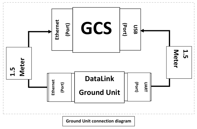
2. 1 × Jednostka naziemna łącza danych połączona z naziemną stacją kontroli (GCS).
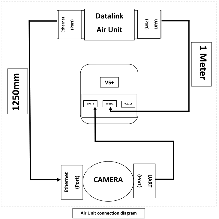
Przepływ danych (przegląd): Dane wideo i czujniki z każdej kamery są przesyłane do powiązanej jednostki Datalink Air za pośrednictwem portu Ethernet kamery. Dane telemetryczne i sterujące pomiędzy FCC a jednostką powietrzną są przesyłane łączem UART. Jednostka powietrzna łącza danych przesyła te strumienie łączem danych do jednostki naziemnej; Jednostka naziemna demultipleksuje strumienie i przedstawia je GCS jako pojedynczy strumień Ethernet (wideo i dane z kamery) i jeden serial (UART-USB) strumień telemetryczny.
Wymagania dotyczące jednostek powietrznych:
Każda jednostka powietrzna łącza danych (jeden na UAV) spełniają następujące obowiązkowe wymagania:
1. Interfejsy & Porty (minimum):
ten 1 × Port UART (minimum). Port ten będzie używany do połączeń telemetrycznych/sterujących z FCC (porty telemetryczne Telem1 / Telem2 w FCC).
ten 1 × Port Ethernet (minimum). Port ten będzie używany do odbioru danych Ethernet z kamery/poszukiwacza.
2. Łączność kablowa (dostarczany z jednostką powietrzną):
ten 1 × Kabel UART (podstawowy) - długość: 1.0 m (±5%). Kabel będzie przenosił TX, RX, GND i VCC. Kabel musi być zakończony odpowiednio do złącza Datalink UART na jednym końcu i złącza telemetrycznego FCC na drugim.
ten 1 × Kabel Ethernet (podstawowy) - długość: 1.0 m (±5%). Kabel powinien być standardowym ekranowanym kablem krosowym Cat5e lub Cat6 ze złączami RJ45.
ten 2 × komplety zapasowe (na jednostkę powietrzną) - tj., z każdą jednostką Air należy dostarczyć dwa dodatkowe kable UART i dwa dodatkowe kable Ethernet (całkowita ilość dostarczana na jednostkę = 3 kable UART, 3 Kable Ethernetowe).
3. Mechaniczny & Fizyczny:
o Kable powinny być oznaczone kolorami (zalecony) i mają wyraźne oznaczenia kierunkowości, jeśli piny nie są symetryczne.
4. Elektryczne/Protokół:
ten UART: Obsługuje typowe szybkości transmisji do co najmniej 921600 bps. Zapewnij konfigurowalne przez użytkownika parametry UART.
ten Ethernet: Przynajmniej wsparcie 100 Działanie Mb/s (Preferowany Gigabit). Obsługa popularnych protokołów transportowych (UDP, RTSP dla wideo i UDP do sterowania) — istnieje możliwość konfiguracji określonego wyboru protokołu.
Wymagania dotyczące jednostek naziemnych:
Jednostka naziemna wykonuje demultipleksację danych ze wszystkich czterech jednostek powietrznych i zapewnia ujednolicony interfejs do GCS. Obowiązkowe wymagania to:
1. Interfejsy & Porty (minimum):
ten 1 × Port UART (przedstawiony GCS). Jednostka naziemna będzie agregować strumienie telemetryczne ze wszystkich czterech jednostek powietrznych i przedstawiać je GCS jako pojedynczy interfejs UART/USB (NP., jednostka naziemna UART podłączona do interfejsu USB w GCS).
ten 1 × Port Ethernet (przedstawiony GCS). Jednostka naziemna będzie agregować strumienie kamer/wideo i danych z czterech jednostek powietrznych i przedstawiać je jako pojedynczy interfejs Ethernet do GCS.
2. Zachowanie agregacyjne:
o Jednostka naziemna będzie przyjmować cztery niezależne przychodzące strumienie danych (po jednym z każdej Jednostki Powietrznej) i demultipleksować je do połączonego strumienia Ethernet i połączonego strumienia szeregowego. Z GCS’ z perspektywy czasu do konfiguracji i monitorowania będzie dostępne tylko jedno łącze Ethernet i jedno łącze UART.
o Agregacja musi zachować adresowanie źródłowe, aby GCS mógł zidentyfikować, który strumień pochodzi z którego Birda. Jednostka naziemna nie utraci informacji identyfikacyjnych każdego ptaka.
3. Łączność kablowa (dostarczany z jednostką naziemną):
ten 1 × Kabel UART (podstawowy) - długość: 400 mm (0.4 m). Kabel umożliwia połączenie portu UART jednostki naziemnej z portem USB GCS (jeśli jednostka naziemna UART jest bezpośrednim UART, dostarczyć kabel przejściowy USB-UART). Kabel musi przenosić TX, RX, GND i VCC.
ten 1 × Kabel Ethernet (podstawowy) - długość: 400 mm (0.4 m). Kabel powinien być ekranowanym kablem krosowym Cat5e/Cat6 ze złączami RJ45.
ten 2 × zestawy zapasowe — dwa dodatkowe kable UART i dwa dodatkowe kable Ethernet dostarczane jako części zamienne z jednostką uziemiającą.
4. Elektryczne/Protokół:
o Agregacja powinna być przejrzysta w odniesieniu do ramek Ethernet dla wideo; w razie potrzeby jednostka naziemna może przepakować strumienie w jeden strumień transportowy, ale musi zachować informacje o czasie i identyfikację źródła dla każdego ptaka.
ten Multipleksowanie telemetryczne: Jednostka naziemna będzie multipleksować czasowo lub pakietować strumienie telemetryczne w pojedynczy strumień UART z wyraźnym ramkowaniem i opcjonalnymi znacznikami umożliwiającymi rozróżnianie komunikatów według identyfikatora ptaka. Protokół używany do multipleksowania musi być udokumentowany i obsługiwany przez oprogramowanie GCS.
Łączność & Specyfikacje kabli
W tej sekcji wymieniono zalecane specyfikacje kabli i złączy, aby zapewnić niezawodne działanie w środowisku powietrznym i naziemnym.
1. Kable Ethernetowe (Jednostka powietrzna -> Kamera i jednostka naziemna —> GCS): Standardowe ekranowane kable krosowe Cat5e lub Cat6 z końcówkami RJ45. Używaj w pełni ekranowanego (STP) kabel, jeśli instalacja charakteryzuje się wysokim poziomem EMI.
2. Długość Ethernetu (Jednostka Powietrzna): 1.0 m ±5%.
3. Długość Ethernetu (Jednostka naziemna): 400 mm ±5%.
4. Kable UART (Jednostka powietrzna -> Telemetria FCC): 4-kabel przewodzący (TX, RX, GND, opcjonalny RTS/CTS). Długość: 1.0 m ±5%.
5. Kabel UART (Jednostka naziemna -> GCS-USB/UART): 400 mm ±5% (Dołącz adapter USB-UART, jeśli jest to wymagane przez GCS).
6. Ekranowanie i uziemienie kabla: Zapewnij wspólną masę i upewnij się, że ekranowanie jest zakończone na jednym końcu, zgodnie z najlepszymi praktykami, aby uniknąć pętli uziemienia. Jeśli spodziewane są wibracje, użyj blokowanych złączy RJ45 lub zatrzaskowych.
7. Zapewnij kable adapterowe do połączenia złączy telemetrycznych Datalink UART ze złączami telemetrycznymi CUAV V5+ (jeśli moduł Datalink nie udostępnia natywnie kompatybilnego złącza).
8. Gdzie kamera obsługuje technologię Power-over-Ethernet (PoE) ale jednostka Datalink Air nie dostarcza PoE, zapewnić wtryskiwacz PoE.
Funkcjonalny & Wymagania protokołu
Kluczowe wymagania funkcjonalne i zalecenia:
1. Identyfikacja każdego ptaka: Każdy strumień danych (wideo lub telemetria) MUSI być oznaczony unikalnym identyfikatorem ptaka, aby GCS mógł mapować strumienie na pojazdy.
2. Schemat multipleksowania: Jednostka naziemna wdraża deterministyczny schemat multipleksowania dla telemetrii (UART) umożliwiając GCS analizowanie i kierowanie wiadomości według Bird ID. 3. Opóźnienie i przepustowość: System minimalizuje dodatkowe opóźnienia agregacji. 4. Niezawodność: Jednostka naziemna musi sprawnie poradzić sobie z chwilową utratą jednej lub więcej jednostek powietrznych i nadal przekazywać pozostałe strumienie do GCS.
5. Interfejs konfiguracyjny: Podaj metodę konfiguracji (szczegółowy dokument) aby ustawić identyfikatory ptaków, Szybkość transmisji UART, i priorytety poszczególnych strumieni.
Zadać pytanie
Twoja wiadomość została wysłana