UAV Datalink System Overview
그만큼 UAV Datalink System is designed to enable reliable, real-time communication, 제어, and monitoring for multiple unmanned aerial vehicles (uavs). The system consists of four UAVs, each equipped with a Datalink Air Unit, ㅏ 비행 제어 컴퓨터 (FCC, 예를 들어, 거짓 V5+), and a camera/seeker, as well as a Datalink Ground Unit connected to a 지상통제소 (GCS).
주요 특징
- 구성: 1 Ground Unit communicating with 4 Air Units via a point-to-multipoint bidirectional link (이더넷 + UART).
- 범위 & 성능: ≥ 80 km line-of-sight with robust video and telemetry links, supporting 1080p video at 30 fps and telemetry/control data at up to 921600 bps.
- 인터페이스: Air Units provide 1 UART port for FCC telemetry and 1 Ethernet port for camera data. The Ground Unit aggregates these streams and presents a single UART and Ethernet interface to the GCS.
- 케이블 & Wiring: Straight-through TTL UART connections minimize latency and complexity. Ethernet cables support standard Cat5e/Cat6 connections with shielding for EMI protection.
- 신뢰할 수 있음 & 지연 시간: Bit error rate < 8×10⁻⁸, data delay < 1 MS, 패킷 손실 < 1%, with FEC, CRC, and ARQ mechanisms to ensure continuous operation.
- System Flexibility: Each data stream is tagged with a unique Bird ID, allowing the GCS to identify and manage individual UAVs. The system continues operating even if one or more UAVs temporarily lose connection.
This Datalink System ensures seamless integration between UAVs, 카메라, and ground control, providing a lightweight, high-performance solution for real-time multi-drone operations.
Data link requirement documents
이 시스템은 16개의 공중 데이터링크 공중 유닛으로 구성됩니다. (새당 한 마리), a single Datalink Ground Unit, 및 지상 제어 스테이션 (GCS). 목적은 인터페이스를 지정하는 것입니다., 케이블 길이, port counts, and acceptance tests so that units delivered by suppliers will interoperate with the existing FCC (비행 제어 컴퓨터), 카메라 (구직자), and the GCS.
데이터 링크를 구축하려면 완전한 솔루션이 필요합니다. ground station 과 4 UAV air 단위. 시스템은 안정적인 통신을 가능하게 해야 합니다., 제어, and monitoring of all UAVs simultaneously. Detailed technical requirements are provided below.
개요:
- 구성: 1 × 지상 제어 장치 (GCU) 의사소통하다 4 × 공중 유닛 (밖으로)
- 통신 유형: 지점 대 다중 지점 양방향 링크 (이더넷 + UART)
- 범위: ≥ 80 km 시선 (로스)
- 작동밴드: 1.4GHz의(L-대역)
- 변조 방식: TDD-OFDM / QPSK / 16-QAM
- 전력 요구 사항: 작동 전압 (12V), 현재 임계값 (2A 이하)
- 온도 범위: -20°C~75°C
데이터 처리량 및 대역폭:
| 모수 | 요구 사항 | 메모 |
| 비디오 데이터 속도 (구직자 당) | 5 - 9 Mbps의 | 1080피@ 30 fps H.264/265 compression |
| 원격 측정 + 제어 (FCC에 따라) | 200 - 300 kbps | UART 기반 양방향 제어 데이터 |
| 총 비디오 처리량 (4 밖으로) | 24 - 36 Mbps의 | 결합된 비디오 업링크 |
| 집계 원격 측정/제어 | 1 Mbps의 | 영상에 비해 미미함 |
| 필요한 총 업링크 대역폭 | ≥ 36 Mbps의 | 와 함께 20% 독립 단기 치료소 + 간접비 ≒ 42 Mbps의 |
지연 시간 및 품질 요구 사항:
| 모수 | 요구 사항 | 메모 |
| 비트 오류율 | < 8×10⁻⁸ | 최대 범위에서 |
| 데이터 지연 | < 1MS | Required for real-time seekeroperation and data transmission |
| 패킷 손실 | < 1% | FEC 포함 + ARQ 메커니즘 |
| 오류 수정 | 독립 단기 치료소 + CRC + ARQ | 원격 측정 안정성을 위해 필수 |
링크예산 & RF 매개변수:
| 모수 | 목표 Value | 메모 |
| 전력을 전송하십시오 (에어 유닛) | 4 – 5 W | – |
| 전력을 전송하십시오 (지상 유닛) | 4 – 5 W | – |
| 안테나 게인 (에어 유닛) | >3dB | 안테나 패턴: 등방성 |
| 안테나 게인 (지상 유닛) | 12 - 18 dB | 지향성 안테나 |
| 수신기 감도 | –103dBm @10 MHz | 10⁻⁵ BER의 경우 |
| 링크마진 @ 80 km | > 10 dB | 강력한 비디오 보장 + 데이터 링크 |
메모:
- For seamless integration between the CUAV V5+ flight controller and external peripherals, UART 직기가 다음을 유지하는 것이 중요합니다. direct and uncomplicated wiring structure. 구체적으로, UART 포트의 직기는 다음과 같이 설계되어야 합니다. single straight line connection without introducing any additional converters or intermediary boards. 이는 잠재적인 실패 지점을 최소화합니다., 대기 시간 감소, and ensures a lightweight and reliable wiring architecture.
- 더욱이, 직기는 트랜지스터-트랜지스터 논리에서 작동해야 합니다. (TTL) voltage levels, V5+ 비행 컨트롤러는 TTL UART를 통해 통신하므로. TTL과의 편차 (RS-232 또는 RS-485 레벨과 같은) would necessitate external level shifters or converters, 이는 직접 직기의 요구 사항과 모순됩니다.. By adhering to TTL standards, 신호 호환성이 유지됩니다, 보장:
- Direct communication between the V5+ and connected modules.
- Reduced hardware complexity by eliminating converters or translators.
- Lower weight and improved reliability, as fewer components are involved in the signal path.
- Improved signal integrity, since additional conversion stages can introduce noise or timing mismatches.
- 더욱이, 직기는 트랜지스터-트랜지스터 논리에서 작동해야 합니다. (TTL) voltage levels, V5+ 비행 컨트롤러는 TTL UART를 통해 통신하므로. TTL과의 편차 (RS-232 또는 RS-485 레벨과 같은) would necessitate external level shifters or converters, 이는 직접 직기의 요구 사항과 모순됩니다.. By adhering to TTL standards, 신호 호환성이 유지됩니다, 보장:
결론적으로,the loom design should strictly provide a straight-through UART wiring harness operating at TTL voltages,aligning with the CUAV V5+electrical specifications and guaranteeing optimal performance in airborne applications.
시스템 개요:
개략적인 시스템 설명:
- UAV 4대, 각각 갖추고:
- 1 × 데이터링크 에어 유닛
- 1 × FCC (비행 제어 컴퓨터, 예를 들어, 거짓 V5+)
- 1 × 시커 / 카메라
- 1 × 지상 제어 스테이션과 연결된 Datalink 지상 장치 (GCS).
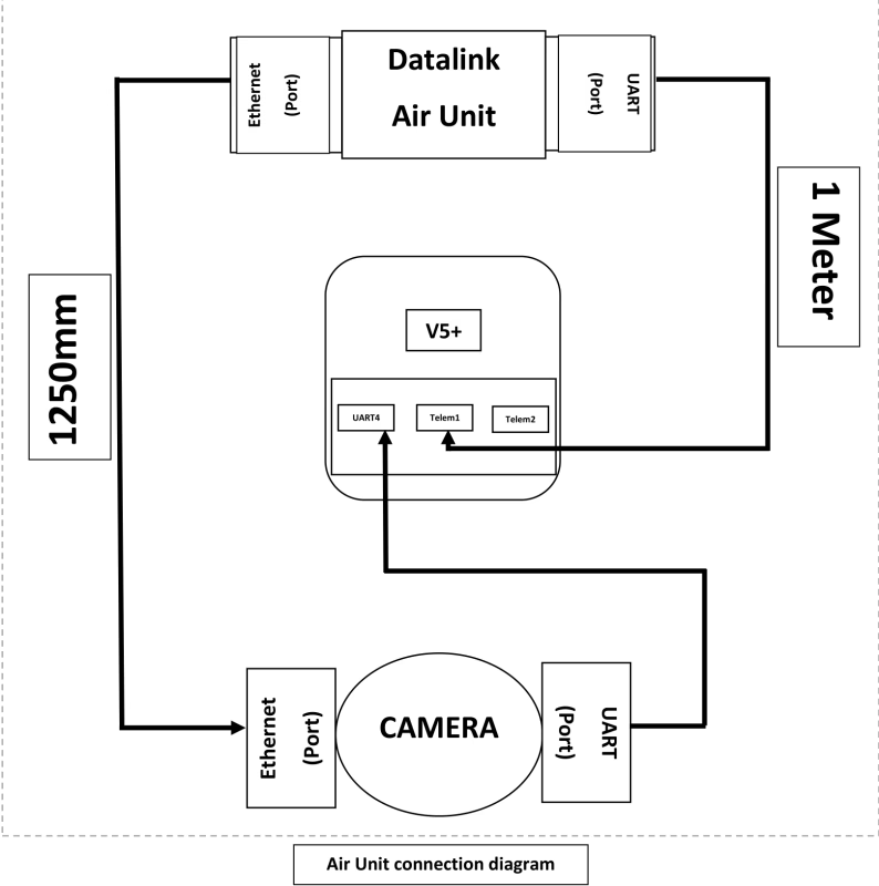
데이터 흐름 (개요): Video and sensor data from each camera is provided to its associated Datalink Air Unit via the camera’s Ethernet port. Telemetry and control data between the FCC and the Air Unit is carried over a UART link. The Datalink Air Unit transmits these streams over the data link to the Ground Unit; the Ground Unit demultiplexes the streams and presents them to the GCS as a single Ethernet stream (카메라 비디오 및 데이터) 그리고 단 하나의 연재물 (UART/USB) telemetry stream.
공중 유닛 요구 사항:
각 데이터링크 에어 유닛 (UAV 당 하나) 다음 필수 요구 사항을 충족해야 합니다.:
1. 인터페이스 & 포트 (최저한의):
- 1 × UART 포트 (최저한의). This port shall be used for telemetry/control connectivity to the FCC (원격 측정 포트 Telem1 / FCC의 Telem2).
- 1 × 이더넷 포트 (최저한의). This port shall be used to receive camera/seeker Ethernet data.
2. 케이블 연결 (delivered with the AirUnit):
- 1 × UART 케이블 (주요한) - 길이: 1.0 미디엄 (± 5%). 케이블은 TX를 전달해야 합니다., RX, GND and VCC. Cable must be terminated to match the Datalink UART connector on one end and the FCC telemetry connector on the other.
- 1 × 이더넷 케이블 (주요한) - 길이: 1.0 미디엄 (± 5%). Cable shall be standard shielded Cat5e or Cat6 patch cable with RJ45 connectors.
- 2 × 예비 세트 (항공 유닛당) - 즉., two additional UART cables and two additional Ethernet cables shall be supplied with each Air Unit (total supplied per unit = 3 UART 케이블, 3 이더넷 케이블).
3. 기계 & 물리적 인:
- Cables should be color-coded (추천) and have clear directionality markings if pinouts are not symmetric.
4. Electrical / 실험 계획안:
UART: 최소 최대 공통 전송 속도 지원 921600 bps. Provide user- configurable UART parameters.
이더넷: 최소한 지원 100 Mbps 작동 (기가비트 선호). Support common transport protocols (UDP, 비디오용 RTSP 및 제어용 UDP) — specific protocol selection shall be configurable.
지상 유닛 요구 사항:
The Ground Unit performs demultiplexing of data from all four Air Units and presents a unified interface to the GCS. 필수 요구 사항은:
1. 인터페이스 & 포트 (최저한의):
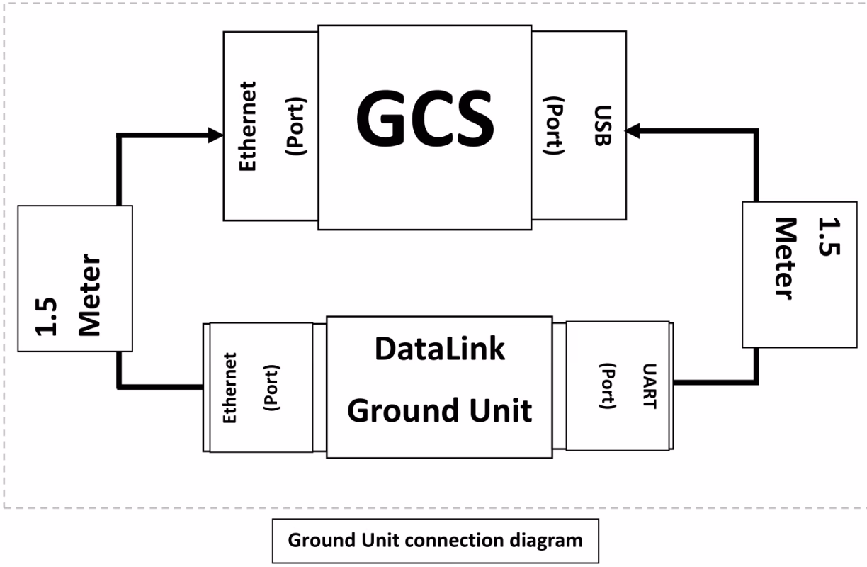
- 1 × UART 포트 (GCS에 제출). The Ground Unit shall aggregate telemetry streams from all four air units and present them to the GCS as a single UART/USB interface (예를 들어, GCS의 USB 인터페이스에 연결된 Ground Unit UART).
- 1 × 이더넷 포트 (GCS에 제출). The Ground Unit shall aggregate camera/video and data streams from the four air units and present them as a single Ethernet interface to the GCS.
2. 집계 동작:
- The Ground Unit shall accept four independent incoming data streams (one from each Air Unit) and demultiplex them to a combined Ethernet stream and a combined serial stream. GCS에서’ perspective there shall be only one Ethernet link and one UART link to configure and monitor.
- Aggregation must preserve source addressing, so the GCS can identify which stream is from which Bird. The Ground Unit shall not lose per-bird identification information.
3. 케이블 연결 (지상 유닛과 함께 제공):
- 1 × UART 케이블 (주요한) - 길이: 400 mm (0.4 미디엄). Cable shall allow connection from the Ground Unit UART port to the GCS USB port (if the Ground Unit UART is a direct UART, USB-UART 어댑터 케이블 제공). The cable must carry TX, RX, GND and VCC.
- 1 × 이더넷 케이블 (주요한) - 길이: 400 mm (0.4 미디엄). Cable shall be shielded Cat5e/Cat6 patch cable with RJ45 connectors.
- 2 × spare sets — two additional UART and two additional Ethernet cables supplied as spares with the Ground Unit.
4. Electrical / 실험 계획안:
- Aggregation shall be transparent with respect to Ethernet frames for video; where needed the Ground Unit may repackage streams into a single transport stream but must preserve timing information and per-bird source identification.
원격 측정 다중화: The Ground Unit shall time-multiplex or packetize telemetry streams into a single UART stream with clear framing and optional tags to distinguish messages by bird ID. The protocol used for multiplexing must be documented and supported by the GCS software.
연결성 & 케이블 사양
This section lists the recommended cable and connector specifications to ensure reliable performance in the airborne and ground environments.
- 이더넷 케이블 (Air Unit -> Camera and Ground Unit -> GCS): Standard shielded Cat5e or Cat6 patch cables with RJ45 terminations. 완전 차폐 사용 (STP) cable if the installation has high EMI.
- 이더넷 길이 (Air 단위): 1.0 m ±5%.
- 이더넷 길이 (Ground 단위): 400 mm ±5%.
- UART 케이블 (Air Unit -> FCC telemetry): 4-도체 케이블 (TX, RX, GND, 선택적 RTS/CTS). 길이: 1.0 m ±5%.
- UART 케이블 (Ground 단위 -> GCS USB/UART): 400 mm ±5% (include USB-UART adapter if required by the GCS).
- 케이블 차폐 및 접지: Provide common ground and ensure shielding is terminated at one end per best-practice to avoid ground loops. Use locking RJ45 or latching connectors if vibration is expected.
Datalink UART와 CUAV V5+ 원격 측정 커넥터를 연결하기 위한 어댑터 케이블 제공 (Datalink 장치가 기본적으로 호환 가능한 커넥터를 노출하지 않는 경우).
- 카메라가 PoE(Power-over-Ethernet)를 지원하는 경우 (PoE) but the Datalink Air Unit does not supply PoE, provide a PoE injector.
기능적 & 프로토콜 요구 사항
주요 기능 요구 사항 및 권장 사항:
- 새별 식별: 각 데이터 스트림 (비디오 또는 원격 측정) MUST be tagged with a unique Bird ID so the GCS can map streams to vehicles.
- Multiplexing Scheme: The Ground Unit shall implement a deterministic multiplexing scheme for telemetry (UART) allowing GCS to parse and route messages by Bird ID.
- 지연 시간 과 처리량: The system shall minimize additional aggregation latency.
- 신뢰할 수 있음: Ground Unit must handle temporary loss of one or more air units gracefully and continue to present remaining streams to the GCS.
- 구성 인터페이스: 구성 방법 제공 (상세한 문서) to set Bird IDs, UART 전송 속도, 스트림별 우선순위.
질문하기
응답해 주셔서 감사합니다. ✨