The system comprises sixteen airborne Datalink Air Units (one per bird), a single Datalink Ground Unit, and a Ground Control Station (GCS). The purpose is to specify interfaces, cable lengths, port counts, and acceptance tests so that units delivered by suppliers will interoperate with the existing FCC (flight control computer), cameras (seekers), and the GCS.
A complete solution is required for establishing a data link between a ground station and 4 UAV air units. The system should enable reliable communication, control, and monitoring of all UAVs simultaneously. Detailed technical requirements are provided below.
Overview:
∙ Configuration: 1 × Ground Control Unit (GCU) communicating with 4 × Air Units (AUs) ∙ Communication Type: Point-to-Multipoint bidirectional link (Ethernet + UART) ∙ Range: ≥ 80 km line-of-sight (LOS)
∙ Operating Band: 1.4GHz(L-Band)
∙ Modulation Scheme: TDD-OFDM / QPSK / 16-QAM
∙ Power Requirement: operating voltage (12V), Current threshold (≤ 2A) ∙ Temperature Range: -20°C to 75°C
Data Throughput and Bandwidth:
| Parameter | Requirement | Notes |
| Video Data Rate (per seeker) | 5 – 9 Mbps | 1080p @ 30 fps H.264/265 compression |
| Telemetry + Control (per FCC) | 200 – 300 kbps | UART-based bidirectional control data |
| Aggregate Video Throughput (4 AUs) | 24 – 36 Mbps | Combined video uplink |
| Aggregate Telemetry/Control | 1 Mbps | Negligible compared to video |
| Total Required Uplink Bandwidth | ≥ 36 Mbps | With 20% FEC + overhead ≈ 42 Mbps |
Latency and Quality Requirements:
| Parameter | Requirement | Notes |
| Bit Error Rate | < 8×10⁻⁸ | At max range |
| Data Delay | < 1ms | Required for real-time seeker operation and data transmission |
| Packet Loss | < 1% | With FEC + ARQ mechanisms |
| Error Correction | FEC + CRC + ARQ | Mandatory for telemetry reliability |
Link Budget & RF Parameters:
| Parameter | Target Value | Notes |
| Transmit Power (Air Unit) | 4 – 5 W | – |
| Transmit Power (Ground Unit) | 4 – 5 W | – |
| Antenna Gain (Air Unit) | >3dB | Antenna pattern: Isotropic |
| Antenna Gain (Ground Unit) | 12 – 18 dB | Directional Antenna |
| Receiver Sensitivity | –103dBm @ 10 MHz | For 10⁻⁵ BER |
| Link Margin @ 80 km | > 10 dB | Ensures robust video + data link |
NOTE:
⮚ For seamless integration between the CUAV V5+ flight controller and external peripherals, it is essential that the UART loom maintains a direct and uncomplicated wiring structure. Specifically, the loom from the UART port should be designed as a single straight line connection without introducing any additional converters or intermediary boards. This minimizes potential points of failure, reduces latency, and ensures a lightweight and reliable wiring architecture.
⮚ Furthermore, the loom must operate at Transistor-Transistor Logic (TTL) voltage levels, as the V5+ flight controller communicates via TTL UART. Any deviation from TTL (such as RS-232 or RS-485 levels) would necessitate external level shifters or converters, which contradicts the requirement of a direct loom. By adhering to TTL standards, signal compatibility is maintained, ensuring:
o Direct communication between the V5+ and connected modules.
o Reduced hardware complexity by eliminating converters or translators. o Lower weight and improved reliability, as fewer components are involved in the signal path.
o Improved signal integrity, since additional conversion stages can introduce noise or timing mismatches.
In conclusion, the loom design should strictly provide a straight-through UART wiring harness operating at TTL voltages, aligning with the CUAV V5+ electrical specifications and guaranteeing optimal performance in airborne applications.
System Overview:
High-level system description:
1. Four UAVs, each equipped with:
o 1 × Datalink Air Unit
o 1 × FCC (Flight Control Computer, e.g., CUAV V5+)
o 1 × Seeker / Camera
2. 1 × Datalink Ground Unit connected with the Ground Control Station (GCS).
Data flow (overview): Video and sensor data from each camera is provided to its associated Datalink Air Unit via the camera’s Ethernet port. Telemetry and control data between the FCC and the Air Unit is carried over a UART link. The Datalink Air Unit transmits these streams over the data link to the Ground Unit; the Ground Unit demultiplexes the streams and presents them to the GCS as a single Ethernet stream (camera video and data) and a single serial (UART/USB) telemetry stream.
Air Unit Requirements:
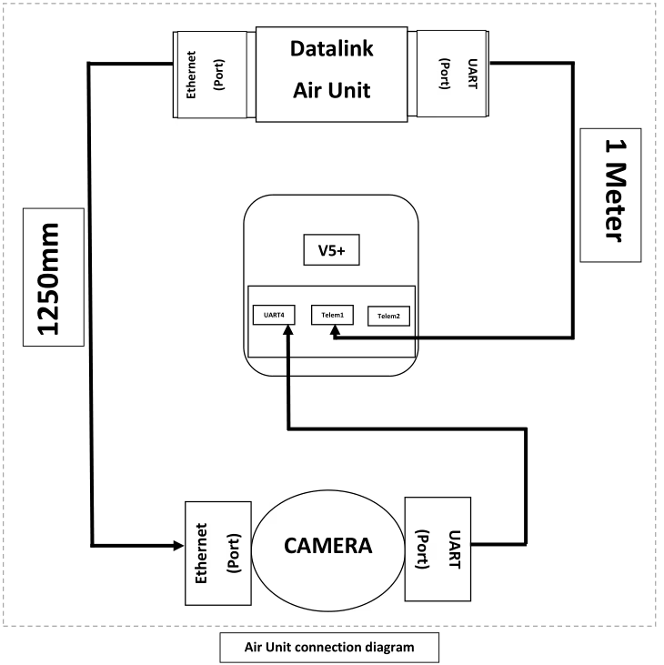
Each Datalink Air Unit (one per UAV) shall meet the following mandatory requirements:
1. Interfaces & Ports (minimum):
o 1 × UART port (minimum). This port shall be used for telemetry/control connectivity to the FCC (telemetry ports Telem1 / Telem2 on the FCC).
o 1 × Ethernet port (minimum). This port shall be used to receive camera/seeker Ethernet data.
2. Cable connectivity (delivered with the Air Unit):
o 1 × UART cable (primary) — length: 1.0 m (±5%). Cable shall carry TX, RX, GND and VCC. Cable must be terminated to match the Datalink UART connector on one end and the FCC telemetry connector on the other.
o 1 × Ethernet cable (primary) — length: 1.0 m (±5%). Cable shall be standard shielded Cat5e or Cat6 patch cable with RJ45 connectors.
o 2 × spare sets (per Air Unit) — i.e., two additional UART cables and two additional Ethernet cables shall be supplied with each Air Unit (total supplied per unit = 3 UART cables, 3 Ethernet cables).
3. Mechanical & Physical:
o Cables should be color-coded (recommended) and have clear directionality markings if pinouts are not symmetric.
4. Electrical/Protocol:
o UART: Support common baud rates up to at least 921600 bps. Provide user configurable UART parameters.
o Ethernet: Support at least 100 Mbps operation (Gigabit preferred). Support common transport protocols (UDP, RTSP for video and UDP for control) — specific protocol selection shall be configurable.
Ground Unit Requirements:
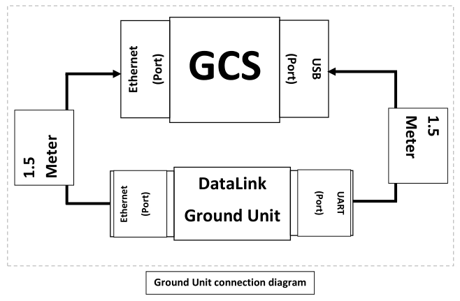
The Ground Unit performs demultiplexing of data from all four Air Units and presents a unified interface to the GCS. Mandatory requirements are:
1. Interfaces & Ports (minimum):
o 1 × UART port (presented to the GCS). The Ground Unit shall aggregate telemetry streams from all four air units and present them to the GCS as a single UART/USB interface (e.g., the Ground Unit UART connected to a USB interface on the GCS).
o 1 × Ethernet port (presented to the GCS). The Ground Unit shall aggregate camera/video and data streams from the four air units and present them as a single Ethernet interface to the GCS.
2. Aggregation behavior:
o The Ground Unit shall accept four independent incoming data streams (one from each Air Unit) and demultiplex them to a combined Ethernet stream and a combined serial stream. From the GCS’ perspective there shall be only one Ethernet link and one UART link to configure and monitor.
o Aggregation must preserve source addressing, so the GCS can identify which stream is from which Bird. The Ground Unit shall not lose per-bird identification information.
3. Cable connectivity (delivered with the Ground Unit):
o 1 × UART cable (primary) — length: 400 mm (0.4 m). Cable shall allow connection from the Ground Unit UART port to the GCS USB port (if the Ground Unit UART is a direct UART, provide a USB-UART adapter cable). The cable must carry TX, RX, GND and VCC.
o 1 × Ethernet cable (primary) — length: 400 mm (0.4 m). Cable shall be shielded Cat5e/Cat6 patch cable with RJ45 connectors.
o 2 × spare sets — two additional UART and two additional Ethernet cables supplied as spares with the Ground Unit.
4. Electrical/Protocol:
o Aggregation shall be transparent with respect to Ethernet frames for video; where needed the Ground Unit may repackage streams into a single transport stream but must preserve timing information and per-bird source identification.
o Telemetry multiplexing: The Ground Unit shall time-multiplex or packetize telemetry streams into a single UART stream with clear framing and optional tags to distinguish messages by bird ID. The protocol used for multiplexing must be documented and supported by the GCS software.
Connectivity & Cable Specifications
This section lists the recommended cable and connector specifications to ensure reliable performance in the airborne and ground environments.
1. Ethernet cables (Air Unit -> Camera and Ground Unit -> GCS): Standard shielded Cat5e or Cat6 patch cables with RJ45 terminations. Use fully shielded (STP) cable if the installation has high EMI.
2. Ethernet length (Air Unit): 1.0 m ±5%.
3. Ethernet length (Ground Unit): 400 mm ±5%.
4. UART cables (Air Unit -> FCC telemetry): 4-conductor cable (TX, RX, GND, optional RTS/CTS). Length: 1.0 m ±5%.
5. UART cable (Ground Unit -> GCS USB/UART): 400 mm ±5% (include USB-UART adapter if required by the GCS).
6. Cable shielding and grounding: Provide common ground and ensure shielding is terminated at one end per best-practice to avoid ground loops. Use locking RJ45 or latching connectors if vibration is expected.
7. Provide adapter cables for interfacing Datalink UART to CUAV V5+ telemetry connectors (if the Datalink unit does not natively expose a compatible connector).
8. Where camera supports Power-over-Ethernet (PoE) but the Datalink Air Unit does not supply PoE, provide a PoE injector.
Functional & Protocol Requirements
Key functional requirements and recommendations:
1. Per-Bird Identification: Each data stream (video or telemetry) MUST be tagged with a unique Bird ID so the GCS can map streams to vehicles.
2. Multiplexing Scheme: The Ground Unit shall implement a deterministic multiplexing scheme for telemetry (UART) allowing GCS to parse and route messages by Bird ID. 3. Latency and Throughput: The system shall minimize additional aggregation latency. 4. Reliability: Ground Unit must handle temporary loss of one or more air units gracefully and continue to present remaining streams to the GCS.
5. Configuration Interface: Provide a configuration method (a detailed document) to set Bird IDs, UART baud rates, and per-stream priorities.
Ask A Question
Thank you for your response. ✨